Sign In
Welcome! Sign In to personalize your Cat.com experience
If you already have an existing account with another Cat App, you can use the same account to sign in here
Register Now
One Account. All of Cat.
Your Caterpillar account is the single account you use to log in to select services and applications we offer. Shop for parts and machines online, manage your fleet, go mobile, and more.
Account Information
Site Settings
Security
Ed Schroeder
Senior Engineering Specialist
Caterpillar Electric Power
Keith Folken
Senior Engineering Specialist
Caterpillar Innovation and Technology Development
October 2016
In facilities with a high demand for power, such as a hospital or data center, communication among generator sets is crucial for maintaining power levels. In these types of applications, generator sets can be electrically connected to help manage the large power need. Called paralleling generator sets, this configuration helps ensure more efficient load sharing and load response within a network.
One way to operate power systems with paralleled generator sets is to use dedicated multi-function engine generator set controllers with integrated paralleling controls on board the generator set. With Cat® EMCP 4.4 control system, the individual controllers communicate with each other by way of an Ethernet backbone, synchronizing the generator sets through a connection to a single Ethernet switch.
This approach to paralleling is cost-effective, as it integrates the function of discrete paralleling control devices and programmable logic controllers with the generator set controls and reduces switchgear footprint, leading to lower project capital cost. However, the approach has raised questions among power system designers and users:
For generator sets equipped with EMCP 4.4 control and Multiple-Generator Data Link (MGDL), the answer is an unequivocal yes. Caterpillar’s patented strategy called Failsafe Adaptive Load Sharing/Droop Operation is programmed into the EMCP 4.4 system to intelligently switch units to a control scheme that enables uninterrupted, stable operation for as long as it takes for full communication to be restored. The communication loss also triggers an alarm that alerts operating personnel to the condition so that repairs can be expedited.
The traditional approach to communication failure in paralleled generators sets carries risks of system instability and unsafe engine operation. In the standard response to communication failure, units are divided into two modes: droop and isochronous. The droop units are automatically placed at a fixed, pre-determined target load level, such as 50 percent load at nominal frequency. The isochronous swing machines, also known as swing machines, take on the majority of load changes. The droop units begin to pick up load only after the isochronous units become overloaded to greater than 100 percent of their rating.
This control scheme has two main disadvantages. First, the droop generator sets may be operating at a different load percentage at the time communication is lost. They must then immediately adjust to the frequency and load on their droop curve. This may mean suddenly adding or lowering their fuel to match the frequency of the isochronous generator sets, which could cause instability in the system and loss of synchronization. The isochronous group can also become overloaded as load increases even after the system is stabilized. Although the droop generator sets could add more load, this design prohibits them from doing so.
Another deficiency of this approach is that it needlessly limits the system’s power capability. The output power of the swing machines changes to follow variations in load, while maintaining a constant speed and frequency on the system. The droop units, with the fixed setting at 50 percent load, will always produce the same power output at a particular speed or frequency. Therefore, the maximum available load for this type of system is limited to the combined output of the swing machines and the total fixed power output of the droop machines. Any load above that maximum will result in a decrease in speed and frequency. If load increases beyond this maximum available load, the swing machines can be overloaded even though the droop units are operating at well below their maximum capabilities.
Furthermore, the minimum system load cannot be allowed to fall below the combined fixed output for the droop units under this control approach. If it does, the system frequency will increase, and the swing machines can become motorized or reverse-powered.
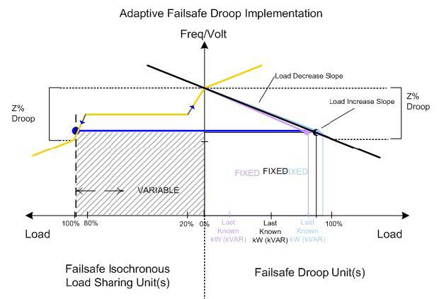
The Failsafe Adaptive Load Sharing/Droop Operation approach using EMCP 4.4 safely maintains stability through a loss of communication, seamlessly transitioning into failsafe mode with gradual, stable movement to a new equilibrium point.
Under this approach, the failsafe mode is triggered when communication messages from one or more EMCP 4.4 units are not received following a specified time interval. The communication loss can result from conditions such as broken wires, improper configuration, power loss to the Ethernet router or hub device, or power loss to an EMCP 4.4 unit.
When communication is lost, the failure mode intelligently switches some lost units to Failsafe Adaptive Droop and other units to Failsafe Isochronous Load Sharing. The operating modes of the units during a loss of communications are updated to best serve the generator system.
For example, if the units that have lost communication are still running and on the bus, it is necessary for them to operate safely. The Caterpillar patented MGDL system uses knowledge of the network topology to be conservative in relation to the missing units. A communication loss results in a split network. Units are separated into an Isochronous Load Sharing Group and a Droop Group based on:
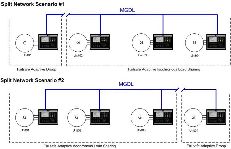
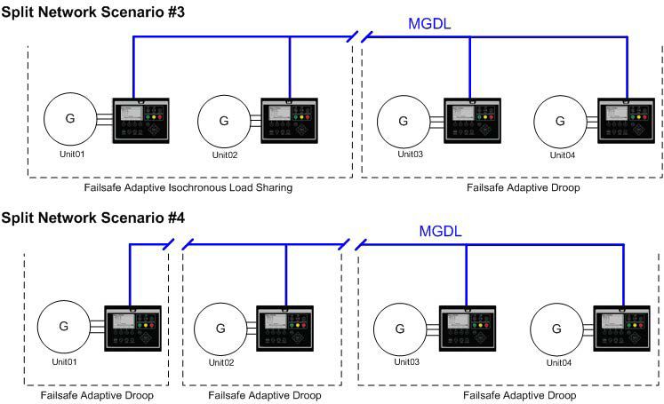
Four basic split network scenarios apply depending on where in the network the break in communication occurs.
Scenario 1. If a controller (Unit 01, for example) detects fewer than half the expected number of controls online (a minority), then the minority operate in the Failsafe Adaptive Droop mode and the balance in the Failsafe Adaptive Isochronous Load Sharing mode.
Scenario 2. If a controller (Unit 01, for example) detects more than half the expected number of controls online (majority), then the majority operate in the Failsafe Adaptive Isochronous Load Sharing mode and the balance in the Failsafe Adaptive Droop mode.
Scenario 3. If a controller detects exactly half the expected number of controls on the network, there are two possibilities. If the control detects the lowest unit number, then that unit and the other units in its half operate in Failsafe Adaptive Isochronous Load Sharing mode, and the other half operate in the Failsafe Adaptive Droop mode. If the control does not detect the lowest unit number, the opposite occurs.
Scenario 4. If multiple splits in the network happen at different times, it is possible to end up with only controls operating in Failsafe Adaptive Droop mode and no controls operating in Failsafe Adaptive Isochronous Load Sharing mode.
One simplified example illustrates how generator sets respond to a communication break under the Failsafe Adaptive Load Sharing/Droop Operation control strategy. In this and other cases, the generator sets follow programmed instructions to move smoothly to a point of equilibrium from which the system responds appropriately to take on or shed load instead of jumping rapidly to some predetermined output level.
No matter if the units are heavily or lightly loaded when the break occurs, the control strategy enables the system to adapt and remain stable. Units respond smoothly to load in a safe, slow manner along pre-programmed load curves. Furthermore, the approach preserves greater system load capacity than in the traditional response to a communication failure.
At the time a communication break is detected, the generator sets in the majority group go into modified isochronous operation, while the generator sets in the minority group go into adaptive droop, initially “freezing” at their last load level. As load increases, the increase is absorbed by the isochronous units. The loads on the droop units do not change.
As load increases further, the isochronous units continue to accept load up to 80 percent of capacity. At that point, the isochronous units resist taking on more load, the frequency drops and the droop units take on more load. A similar process plays out as load decreases.
The Failsafe Adaptive Load Sharing and Failsafe Adaptive Droop modes have two basic effects:
The Failsafe Isochronous Load Sharing and Failsafe Adaptive Droop modes are intended for failsafe operation only and not for normal operation over long periods. While a generator system operating in failsafe mode will serve system load adequately, normal MGDL load sharing is a more robust and stable operating mode.
After the failsafe modes are activated, the system requires investigation. An alarm indicates when communication loss has occurred. This can take the form of a flashing light, an audible signal, a text message or call to operators’ smart phones, or some combination of these, depending on how the alarm system is configured. On receipt of the alarm, proper troubleshooting steps should be taken as soon as possible to return the system to normal operation.
The load sharing protocol is designed to enable transition to and from the failsafe modes as seamlessly as possible, although that cannot be absolutely guaranteed. Changes to load sharing-gains and system loading significantly affect the ability to transition between the failsafe and normal operating modes without disturbance.
In summary, the Failsafe Adaptive Load Sharing/Droop Operation control strategy offers a unique advantage in providing stability even after a single-point failure in a multiple-generator-set power system.
About the Authors
Ed Schroeder is a senior engineering specialist with Caterpillar Electric Power.
Keith Folken is a senior engineering specialist in the Innovation and Technology Development division at Caterpillar.