TODAY’S GENERATOR SET PARALLELING SOLUTIONS
The paralleling of generator sets is as much of an art as it is a science. Each EPS installation is as unique as the individual customer’s power needs and the design engineers involved in its development. Perhaps more importantly, the science employed is impacted by the budgetary constraints of the project. All of these factors have resulted in an evolution to the strategies used in paralleling generator sets. The following pages contain three high level categories used to describe those strategies. While the terminology used may differ by manufacturer, you will find that the solutions offered fit one of the three main categories. Hybrid solutions involving any combination of the approaches are also implemented in an ongoing effort to meet customer requirements in a creative and cost-effective manner.
ON-GENERATOR SET PARALLELING CONTROLS
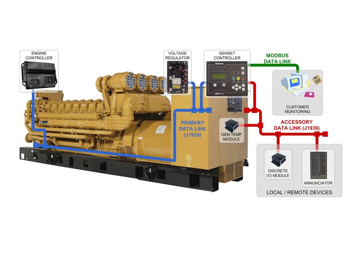
On-generator set paralleling controls refer to dedicated microprocessor-based synchronizing and paralleling controls located on the package generator set. In this case, the synchronizing control operations are combined with the more basic generator set control functions into a single generator set controller. This method of paralleling has proven to be a simple and economical solution, when basic system functionality is required. These paralleling solutions are normally limited to standard paralleling configurations and often paired with generator-mounted circuit breakers or another disconnect means (i.e., contactors) to connect the generators electrically. These multi-function control devices will include the basic functions expected in traditional paralleling control systems: dead bus arbitration, manual/automatic synchronizing, real (kW) and reactive (kVAR) load sharing and load shed/load add functionality. More advanced control systems will also include the ability to automatically cycle generator sets on and off of a common electrical bus based on load demand (“load sense / load demand”).
Where additional master control capability is not employed, the systems are frequently limited to isolated common bus applications (multi-unit island mode/ standby emergency or prime power configurations) or single generator to utility paralleling scenarios. Applications that require a complicated sequence of operation are not well suited for on-generator set paralleling solutions due to the cost and complexity to apply the system on-site.
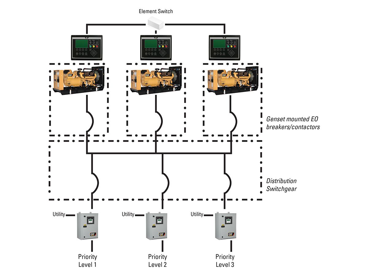
Typical on-generator set paralleling applications are often limited to low voltage applications (<600V), because of concerns related to the mounting of controls on the package at higher voltages. Medium voltage applications may use similar controls and designs, but are mounted remotely in more of a controls only configuration, which will be covered later in this document. In low voltage applications, the output of the generator set connects to distribution switchgear/switchboard as shown in the sample single line below in Figure 1. In this sample system, the three generator sets equipped with on-generator set paralleling controls connect to a main (common) electrical bus via a generator set-mounted electrically operated circuit breaker. While other methods of connecting/ disconnecting to a bus can be used, it is imperative that the speed of the switching device be sufficient for the synchronizing function (i.e., 5 cycle close/open) to prevent out-of-phase paralleling. Further, this switching function may be performed at the generator itself or at the distribution switchgear. Typical installations also include automatic transfer switches fed from the common bus and controlled by the output of the generator set-mounted controller. More advanced control systems will allow for prioritized shedding and re-adding of downstream loads via the transfer switches with or without the aid of a separate master control device (represented in Figure 1).
Pros
The primary benefit of this type of system is the hardware cost. Combining the synchronizing functions with generator set controls, in and of itself, has proven to reduce the upfront cost of the system. Further, this method often serves to reduce the cost and footprint of the distribution switchgear since the synchronizing controls do not take up space in the switchgear. In short, package mounted paralleling systems have proven to provide price competitive solutions.
On-generator set paralleling systems are characteristically low in complexity, with predefined operation and capability. They are relatively simple to learn and operate. They also offer consistent designs for given applications, as they do not rely on the variabilities found in other technologies, such as Programmable Logic Control (PLC) systems, which require programming and logic that will differ by system integrator. These systems often afford a short lead time when included as part of a factory-based generator set solution, which provides the added advantage of being part of the factory assembly and testing process of the generator set.
Cons
Some of the same characteristics that make on-generator set paralleling systems appealing become drawbacks of the technology. The predefined operation of the control device limits the feature sets and flexibility of the system. By comparison, the PLC technology often used in paralleling switchgear systems enables greater design flexibility. When applying on-generator set paralleling solutions, care must be given to ensure that features of the technology meet the requirements of the intended application. This includes system sequence of operation as well as any site integration requirements.
Some of the limitations related to the flexibility of these systems may be overcome through the addition of system master controls. Whether these controls are supplied in wall mount or freestanding control panels, they often provide additional system level monitoring and control which expands the capability of the generator set-mounted controls.
As additional capabilities are added to the on-generator set paralleling device, the on-site integration and setup grows more complicated. Further setup, wiring and testing may be required to validate the installation and should be considered when evaluating the total cost to apply this type of system.
PARALLELING CONTROLS ONLY
There are systems, such as in medium and high voltage generator set applications, where the preference is to keep the paralleling controls separated from the generator sets as well as from the distribution switchgear. For these types of applications, paralleling controls-only solutions are available. In this strategy, the synchronizing controls are installed in a wall mount control panel or freestanding cabinet and may consist of either dedicated controllers similar to those used in the on-generator set solution, PLC control systems or some combination of both technologies.
Much like on-generator set paralleling controls, these solutions tend to include pre-defined paralleling configurations, where the generator sets connect directly to the distribution switchgear/switchboards and control downstream automatic transfer switches or distribution circuit breakers. However, when PLCs are employed, these systems can become quite flexible and include advanced solutions such as utility paralleling.
Although these systems are not available from all control or generator set manufacturers, they are commonly viewed as a platform for master level control when applied with on-generator set paralleling controls, and often include options for more advanced touchscreen HMI for operator interface to the system. Additionally, these solutions may also be optionally equipped with utility paralleling capability or redundant PLC configurations which meet higher level industry specifications.
Pros
In a similar approach to the on-generator set paralleling solutions, controls-only solutions are typically equipped with standard componentry and offer pre-defined operating sequences, which result in shorter lead times as compared to integrated paralleling switchgear solutions. However, custom designs can be more easily developed in this platform, offering more complex solutions with greater feature sets and the flexibility to meet a wider variety of application needs.
Controls-only solutions have also proven to be an excellent retrofit solution. They enable customers to apply advanced control and monitoring capabilities to legacy generator set controls, different generator set manufacturers and to existing switchgear.
Based on their ability to provide standard system controls or more complex operations, product cost for controls-only solutions range from being price competitive with on-generator set solutions to a significant cost premium for more complex alternatives.
Cons
To be cost competitive, standard controls-only solutions have been developed to meet similar system control functions as offered by the on-generator set alternative and are often limited in their level of customization. They also tend to be limited in their level of redundancy, as compared to integrated paralleling switchgear designs based on PLC system controls. Furthermore, the controls-only solutions are likely not to be equipped with the utility grade protective relay devices supplied in paralleling switchgear solutions.
As is the case with on-generator set paralleling solutions, it should be recognized that switchgear remains necessary for proper system operation and must be accounted for when designing controls-only systems. Also, interconnection between these controls and the distribution switchgear is primarily completed on-site and not within the controlled environment of a manufacturing facility. Accountability for the integration of the electrical system must be determined at an early phase in the project cycle and considered in the overall cost of the installed system.
PARALLELING SWITCHGEAR
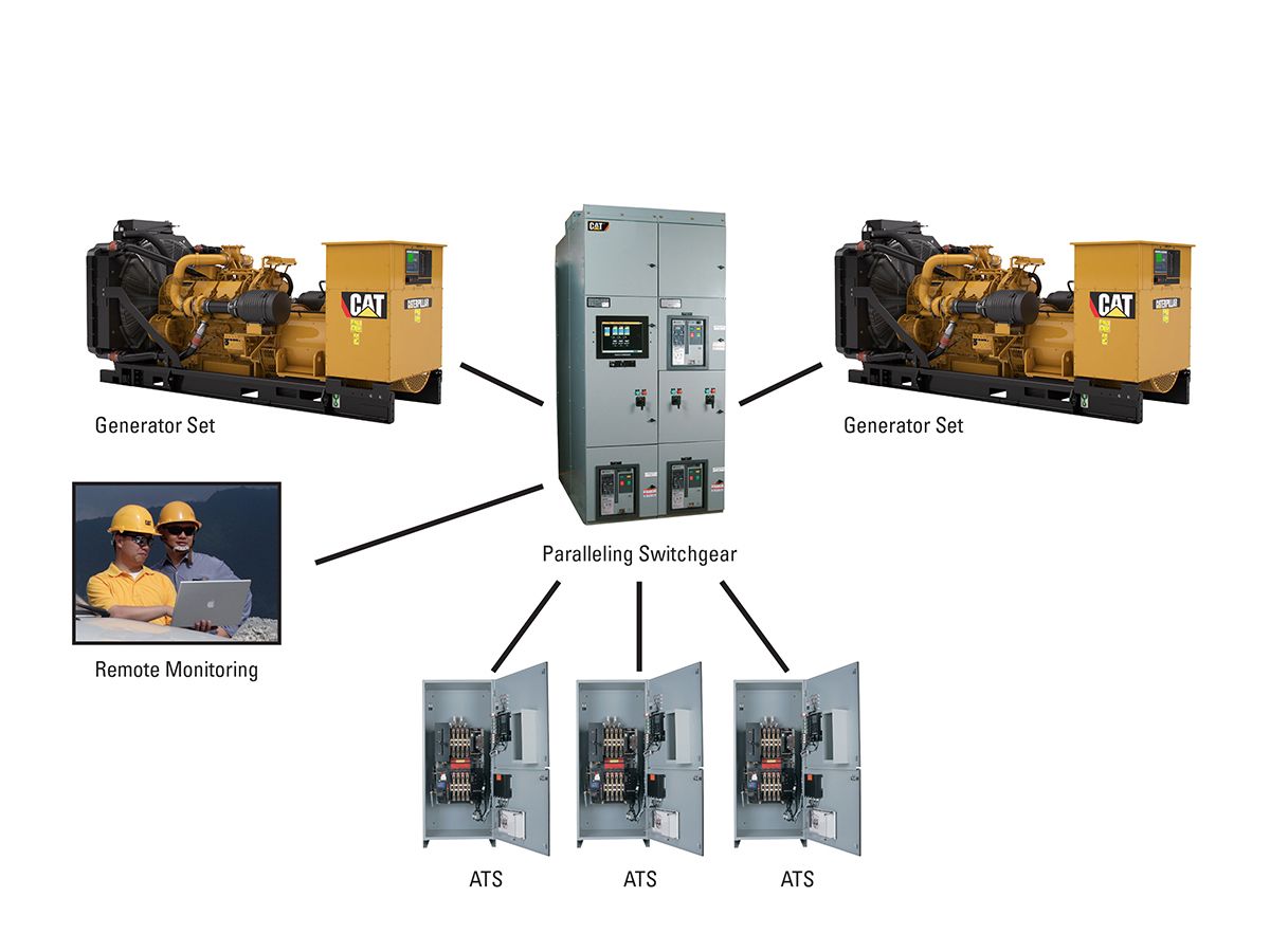
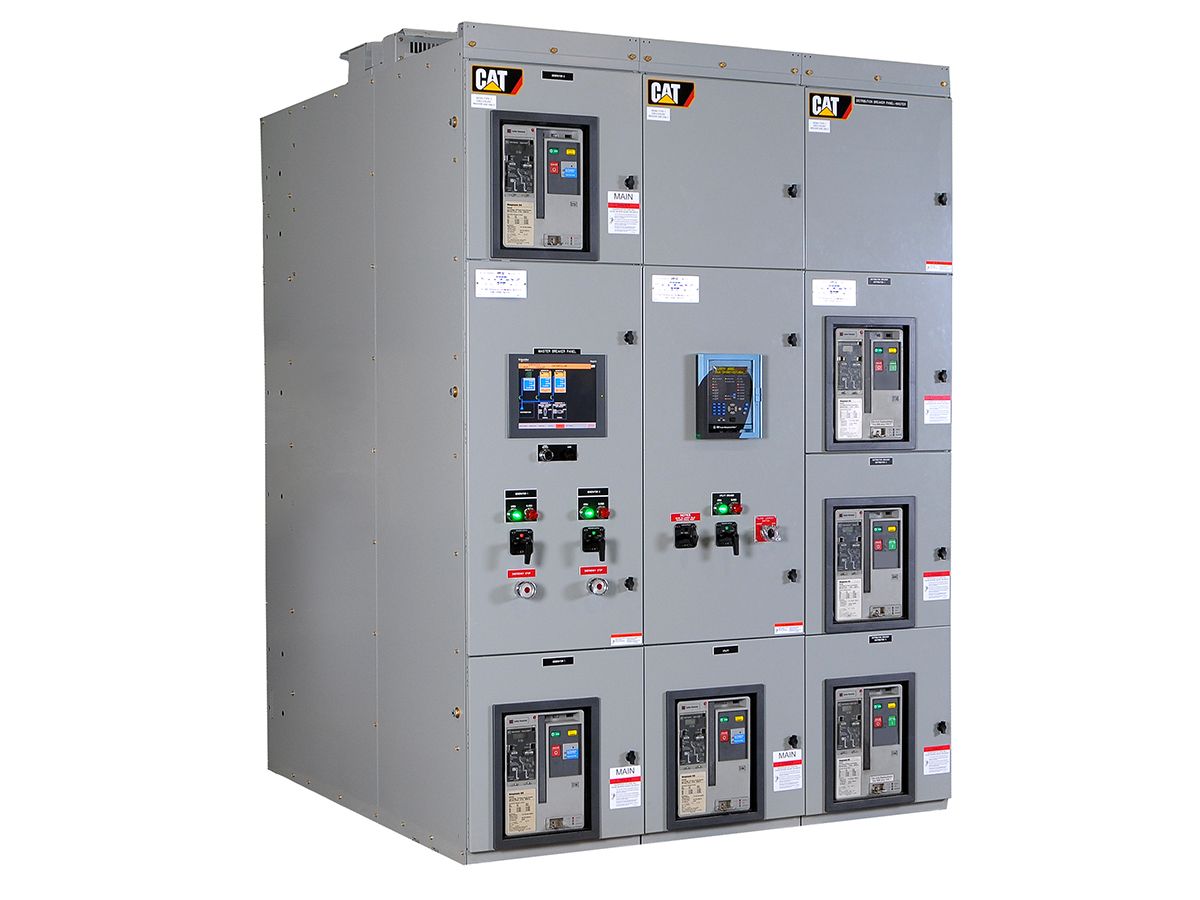
The integration of paralleling controls within the construct of distribution switchgear is a traditional paralleling strategy that has served global markets for many years. Over the years, the controls have evolved from the use of discrete synchronizing and protective devices to more streamlined solutions featuring multi-function controllers, PLCs and a color touchscreen operator interface. See an example in Figure 2. Switchgear featuring “glass and metal” analog meters, paralleling swing panels, discrete control devices and auxiliary “ice cube” relays have been streamlined, while still providing the reliability and operability demanded in the most sophisticated operating environments. This evolution has enabled increased functionality with fewer components and a shrinking footprint of the paralleling switchgear lineup, reducing customer investment in areas of EPS operation.
Pros
Integrated paralleling switchgear solutions afford the greatest number of benefits to a customer’s EPS. While the cost premium is often perceived to be substantial over more cost advantage alternatives, paralleling switchgear remains the most feature-rich of the options.
First, the paralleling controls are fully integrated within the switchgear/switchboard and tested for integration and functionality in the more controlled environment of a factory. By comparison to other methods, this serves to limit the amount of integration performed in the field where site conditions may complicate this work and the commissioning process. As required by the given application, controls may be integrated with metal enclosed, metal clad, arc-protected or even arc resistant switchgear.
The level of customization capability is maximized with integrated paralleling switchgear. Solutions range from the simplest of multi-unit island mode applications to the most complex multi-utility paralleling configurations. Options for redundant automation controllers, control networks and protective relay configurations are available for the highest levels of system reliability. Advanced and complex sequence of operations can be developed to improve overall system reliability and ease of operation. This paralleling strategy affords the greatest opportunity to meet references found in traditional engineering specifications and offers designers the highest level of system flexibility.
Customizable system HMI solutions for control and monitoring also serve to differentiate paralleling switchgear. In this environment, solutions can provide users with an integrated view and operation of an entire facility. Options can be provided to enable users a variety of HMI experiences including the ability to view data from the various components (UPS, ATS, generator set, load banks, etc.) located throughout the customer’s facility, as well as integrate with the customer’s Building Management System (BMS). Fully featured systems also include system level logging, trending and reporting with built-in state-of-the-art fault alerts.
Cons
The higher cost of paralleling switchgear solutions, whether actual or perceived, has become the single biggest deterrent to using this strategy. While the cost impact of integrating paralleling controls and distribution switchgear on-site is often overlooked in comparing the cost of alternative methods, the feature-rich paralleling switchgear strategy is increasingly being viewed as a cost premium approach to paralleling generator sets.
SUMMARY
A variety of solutions and strategies are available when paralleling generator sets. The three general approaches discussed in this document offer their own advantages and disadvantages and deserve consideration in the development of an emergency power system. On-generator set paralleling schemes have proven to be a cost-effective means of providing standard paralleling functionality for a pre-configured solution. Controls-only offerings build on the standard features found in the on-generator set products and provide further system level flexibility, while serving as an excellent alternative for generator set paralleling retrofits. Integrated paralleling switchgear provides the greatest level of flexibility in the design and integration of all the site’s key power components.
CONCLUSION
With the assistance of a solutions provider able to deliver a balanced view of all available technologies, an emergency power system can be developed to optimize a design solution and meet site requirements most efficiently.
What must be remembered is that there is no “one size fits all” solution. Each site application must be evaluated based on feature needs, design complexity and project budgets. In that regard, the paralleling of generator sets and emergency power system design remains as much of an art as it is a science.
ABOUT CATERPILLAR
For more than 90 years, Caterpillar Inc. has been making sustainable progress possible and driving positive change on every continent. Customers turn to Caterpillar to help them develop infrastructure, energy and natural resource assets. With 2016 sales and revenues of $38.537 billion, Caterpillar is the world’s leading manufacturer of construction and mining equipment, diesel and natural gas engines, industrial gas turbines and diesel-electric locomotives. The company principally operates through its three product segments – Construction Industries, Resource Industries and Energy & Transportation – and also provides financing and related services through its Financial Products segment. For more information, visit caterpillar.com. To connect with us on social media, visit caterpillar.com/social-media.


