
My Account
Sign In
Welcome! Sign In to personalize your Cat.com experience
If you already have an existing account with another Cat App, you can use the same account to sign in here
Register Now
One Account. All of Cat.
Your Caterpillar account is the single account you use to log in to select services and applications we offer. Shop for parts and machines online, manage your fleet, go mobile, and more.
Welcome Back!
My Account Dashboard
Account Information
Site Settings
Security

Designing power systems for co-location data centers
Engineers must consider many factors when designing power and electrical systems for data centers.
Learning objectives
- Understand the key design factors in co-location facility electrical design.
- Learn about the role of the service-level agreement (SLA) in co-location facility design.
- Recognize standard data center and co-location electrical system topologies and why they are selected.
Providing continuous, high-quality electrical power is among the most important obligations of the co-location data center owner. Electrical engineers must consider many factors when designing power/electrical systems for these co-location facilities. Issues such as backup, standby, and emergency power systems must be incorporated. Co-location facilities differ slightly in that they may have metered/submetered power systems or power based on occupancy measurements.
Co-location data centers are facilities where data center rack space is rented out to companies that require secure and reliable data center space. They provide secure computing space for companies so that they can spend time on their core business rather than operating data centers. Co-location building owners’ business model requires that they push the envelope of design to remove unnecessary components, increase efficiency, and prioritize design decisions to meet the terms of their contracts. The design engineer for co-location owners must understand these drivers and design a system that supports the co-location business model.
Project economics
The co-location business is highly competitive, and the decision to build a new co-location facility is largely based on how much it costs to build and operate versus how much the co-location owner can charge its clients for that space. As such, co-location owners know how much the project needs to cost to achieve their return on investment (ROI) and how much land can be used per kilowatt of information technology (IT) space, among other things.
Prior to beginning design, find what the key conditions of satisfaction are to meet the cost metrics. Questions to answer include:
- What are the key financial-performance indicators for the co-location; i.e., are they low operational cost, first cost, etc.?
- Does the owner have purchasing agreements with specific vendors that you can use for a basis of design, or does the design need to be vendor-agnostic? Beware of using technologies as the design basis that enable only a single bidder to comply with the design.
- What is the site size? This will determine future expansion plans and help establish “no-fly” zones for site utilities.
- What is the site location? This will largely determine the mechanical cooling methodology, which will account for the majority of the non-IT load.
- Who are the other tenants and what are their portions of the total power?
- What are the key cost drivers that determined this site selection? Do they include:
- The cost of power? Low power costs may allow for less efficient cooling methods if they are required by the climate.
- The cost of land? If the cost of land is high, this may drive a multifloor design with a compressed yard space.
- The cost of onsite labor? If the cost of onsite labor is high, this may drive a decision to use modular data centers or modular premanufactured equipment that is largely assembled prior to shipment onsite.
- Tax incentives that require a certain energization date?
- Maintenance costs and part availability?
Codes and standards
It is critical that the system designer determine the codes and standards that apply to most co-location designs. Codes and standards that apply directly to the co-location design include:
- Local approved building codes, e.g., the International Building Code (IBC).
- NFPA 70: National Electrical Code (NEC). Many sections of the NEC will apply to a co-location installation, with the most important being Articles 445 (Generators), 645 (Information Technology Equipment), 646 (Modular Data Centers), 700 (Emergency Systems), 701 (Legally Required Standby Systems), 702 (Optional Standby Systems), and 705 (Interconnected Electric Power Production Sources).
- NFPA 70E: Standard for Electrical Safety in the Workplace.
- NFPA 110: Standard for Emergency and Standby Power Systems (depending on the use of the generators).
Mission critical installations:
- Uptime Institute classifications.
- Telecommunications Industry Association (TIA) 942: Telecommunications Infrastructure Standard for Data Centers.
- ASHRAE 90.4: Energy Standard for Data Centers.
Service–level agreements (SLA)
When determining the programmatic requirements of a co-location, the first step is to understand the terms of the SLA for the co-location owner. The SLA will define the terms of the contract between the co-location owner and their clients and will include items and metrics that will directly influence the design. The SLA may include items such as:
- Temperature/moisture level including variances, rate of rise, excursions allowed per year.
- Voltages served to racks.
- Redundancy of components.
- Reliability/availability metrics.
- Planned outage time per year.
- Unplanned outage time per year.
- Outage response time.
- Physical security.
- Site security.
- Networking and network providers available.
- Power factor and total harmonic distortion (THD).
- Site support hours and level of support.
- Metering locations and billing methodology.
- Certifications and classifications (Uptime Institute or others).
Clearly, an SLA that allows for no planned outage time per year would result in a drastically different design than one that does. Similarly, if the SLA details where power monitoring will be installed for billing purposes, it will have a direct effect on the location of meters, current transformers, and voltage transformers. Understanding the key contractual metrics between the co-location owner and their clients will assist in making proper design decisions.
IT load
Often during the design phase, the co-location owner will not have a customer under contract for the space. When designing the co-location space absent firm client requirements, determine and document the following IT load assumptions:
- Are the IT loads dual- or single-corded?
- What voltage is required at the rack? Not long ago, most racks used 208/120 Vac distribution. However, 415/240 Vac is increasingly being distributed to the rack.
- Are pathways to future racks required in the design?
- Is there an assumed kilowattage per rack or row?
- Are there cabinets/racks that have a much higher electrical density?
- How many racks per row?
- Is power required for in-rack cooling solutions (accommodation for additional electrical power, some possibly on an uninterruptible power supply, or UPS)?
These answers will help determine the size and quantity of the distribution from the UPS to the data center space.
HVAC/mechanical system design
The HVAC system design is beyond the scope of this article; however, the general rule is that the electrical system design must support the redundancy requirements of the mechanical system. If the mechanical system is designed to be concurrently maintainable, the electrical system that supports it typically is as well.
The mechanical systems may be fed off of the critical systems or a centralized system designed to service the entire co-location facility. Regardless of which approach is used, a careful analysis is required of both the mechanical design and the associated supporting electrical design, to ensure that the required level of redundancy is provided to the co-location.
Safety
While there are certainly many design considerations required to develop a safe design, for the electrical designer it is critical to anticipate arc flash mitigation upfront. It is paramount to design systems that eliminate energized work as much as possible, and where it is not possible, to reduce the incident energy.
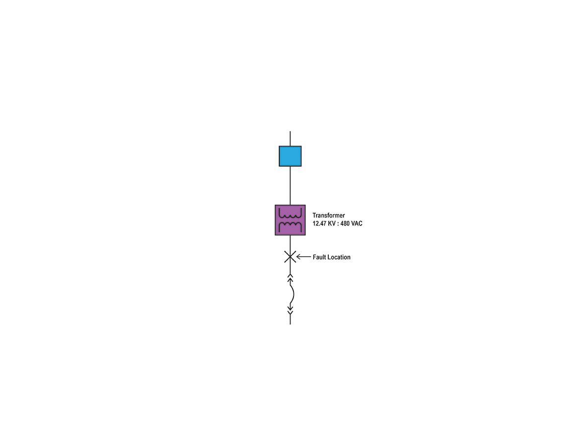
For elimination of energized work, refer to the section in this article titled “Redundancy requirements and topology.” Experience with arc flash studies indicates that the most common areas for high-incident arc energies are the secondary transformers and the associated line side of the secondary switchgear as shown in Figure 1.
Primary-side overcurrent protection will rarely detect a secondary fault fast enough to significantly lower arc flash incident energy. To mitigate this, make sure to specify equipment that has the capability of mitigating or eliminating the arc flash danger. Recommended approaches include:
- Provide transformer disconnecting means that allow a single transformer to be de-energized at a time. This will increase the likelihood that the transformer will be de-energized during maintenance.
- Incorporate differential relaying across the transformer. This will require the installation of current transformers at both the primary and secondary side of the transformer.
- Install infrared (IR) windows or continuous thermal monitoring to avoid exposure the energized transformer secondary while performing thermal scans of the transformer and switchgear terminations.
- Use high-resistance grounding (HRG) at the transformers to reduce the likelihood of a single-phase fault propagating to a 3-phase fault.
- Use optical sensors tied to the upstream breaker to initiate a trip of the breaker.
- Avoid the use of switch/fuse construction as the only means of fault interruption on the primary side. Use of either breakers or vacuum fault interrupters will allow for earlier primary side trip initiation from a secondary fault.
Site development
Most co-location facilities are part of a large campus development, which will include several separate co-locations. If this is a new site development, then a few basic questions need to be resolved:
- Is a new substation required? If so, will it be purchased, constructed, or owned by the client or the serving utility?
- Will the client take service at transmission or distribution voltage from the utility?
- What is the serving voltage? Higher service voltages—for example, 34.5 kV—will make technologies such as air-insulated switchgear (AIS) less appealing due to the space required for AIS at higher voltages.
- What are the projected loads of the initial build-out and the final future campus? This will impact the substation design as well as the size of the components in the medium-voltage system. For example, if both the Day 1 and final build-out demand is 66 MVA, three (3) 33 MVA in a 2+1 configuration will most likely be installed today. However, if the Day 1 load is 10 MVA with a final build-out to 66 MVA in the distant future, two 12-MVA transformers may be installed in a 1+1 configuration today and then be upgraded later as the facility expands.
- How many “meet me rooms” (MMRs) will be required for the site and for the data center you are designing? MMRs are rooms where multiple telecommunication carriers deliver service to the co-location. MMRs frequently require a separate electrical distribution system from the data center’s electrical distribution.
Medium-voltage equipment type and topology
This section assumes that the substation at the transmission level is owned by the utility or will be designed by a firm that specializes in that type of design. The different co-location operators have a wide variety of medium-voltage topologies that they employ, but they are generally a variant of two key types.
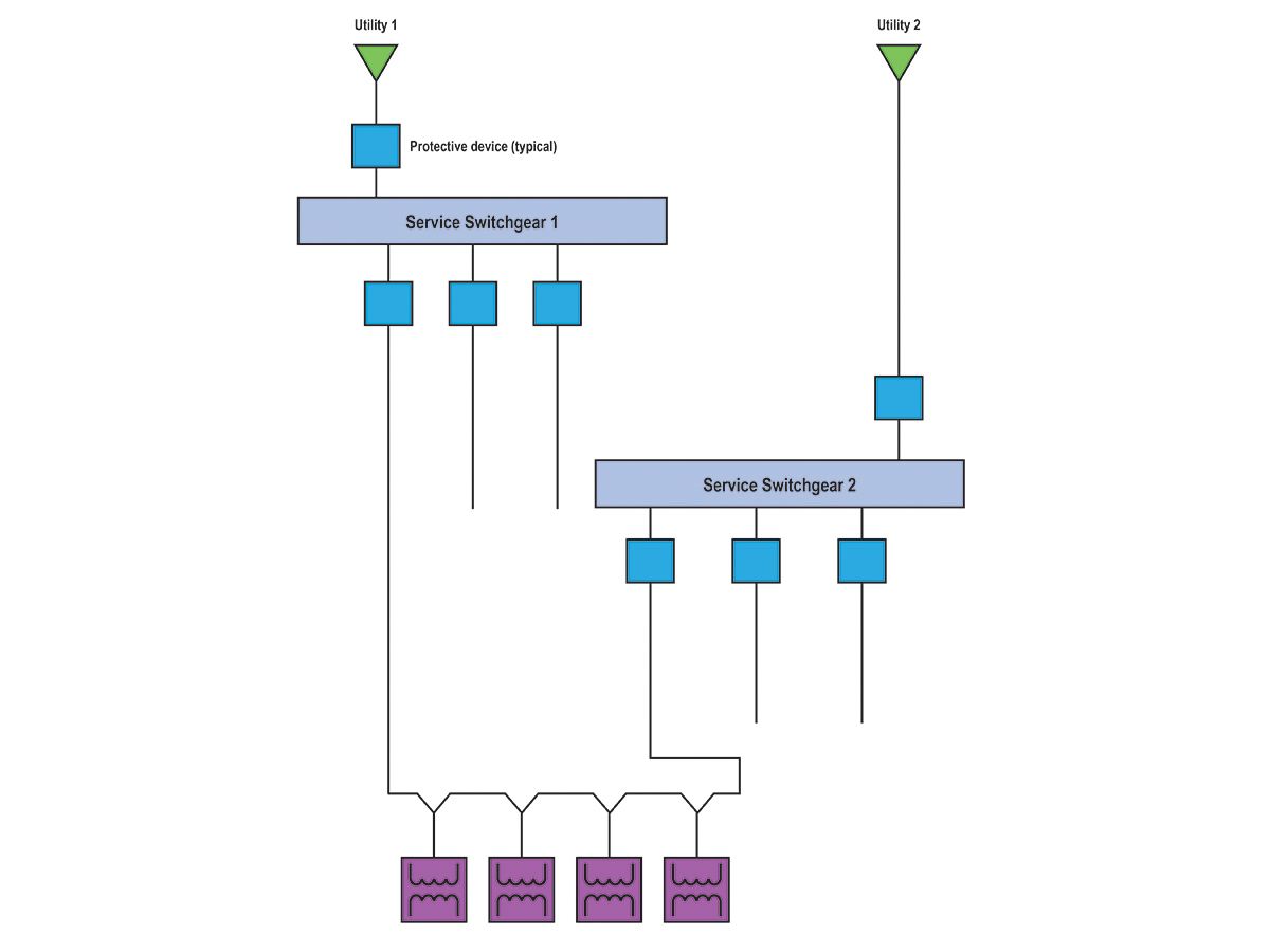
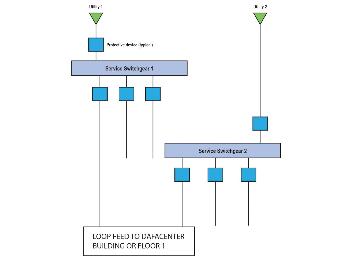
Loop system: The loop system, as shown in Figure 2, is economical and reduces the overall number of switchgear sections located at the service and reduces the number of feeders from the service switchgear to the data center. This type of system often employs switch fuse construction at the transformer to allow for segmentation of the loop.
Loop systems reduce the breaker count and reduce the number of medium-voltage feeders. The disadvantages of this system include:
- More complicated switching for operations staff.
- If switches are used and automation is required, it requires switches with motor operators to provide automatic switching.
- At higher voltages, load break switches have a very low number of operations allowed before requiring service (refer to IEEE Standard C37.20.4-2013 for additional detail).
- As mentioned previously, reducing arc flash at the secondary of transformers when using switch/fuse construction can be difficult.
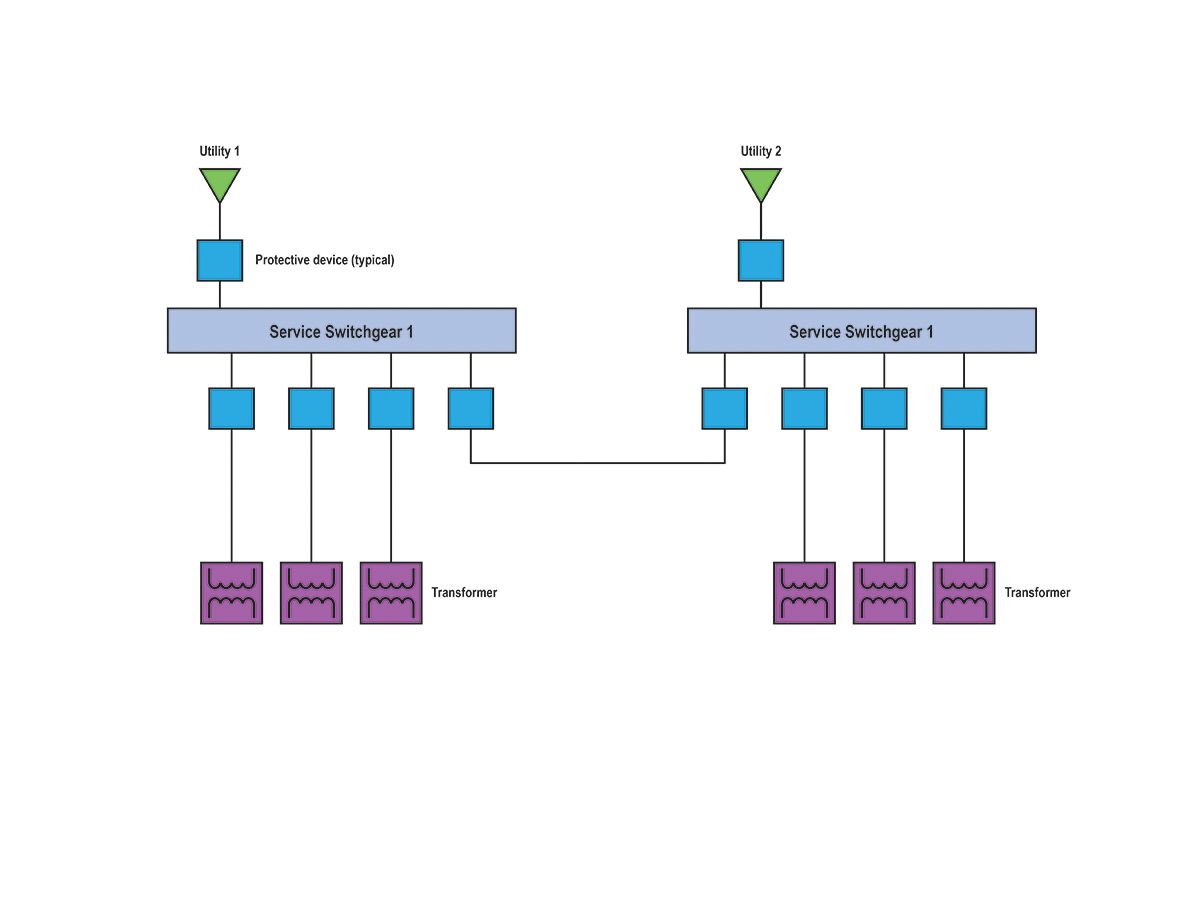
Radial feeders with ties: To avoid some of the disadvantages with the loop system, many owners choose to employ a radial system with ties located switchgear as shown in Figure 3. As with the loop-fed system, any one utility feed can be powered down and power will be maintained through the tie breakers. This eliminates the need for complicated switching downstream from the medium-voltage switchgear and allows for reduction of arc flash energy on the secondary side of the transformer. The disadvantages include:
- Higher first costs due to the increased number of medium-voltage breakers and feeders.
- More complicated switching is required on the secondary side of the transformers to completely remove medium-voltage switchgear from service.
Generators
The generator plant is key to the operation of the co-location. Generator plants are so critical to the operation of any data center that the Uptime Institute considers the generator plant the primary source of power and the utility as an economic backup. Generator selection is a separate topic by itself; please refer to Designing Backup, Standby, and Emergency Power in High-Performance Buildings for additional information.
The key factors to determine for data center generator plants are:
- Rating: Generators are available in either standby, prime, or continuous ratings. Co-location operators generally select either standby, which can produce their nameplate-rated output but has limited average power output over 24 hours, or continuous-rated generators, which can supply to a constant nameplate load without run time restrictions.
- Generator configuration: Single generator systems are the simplest to design and will generally have a shorter lead time than generators that must operate in parallel. Parallel generator systems typically are used when using medium-voltage generators or when there is a desire to use a large generator plant to avoid stranding-generator capacity in single-generator installations. Please refer to Paralleling Generator Systems (Leslie Fernandez, 2016) for additional information.
- Whether there are critical-load generators being used to serve emergency (NEC Article 700) or legally required standby (NEC Article 701) loads. If so, there will be many code requirements for this installation that may complicate the generator installation. It is a good idea to avoid placing these loads on the mission critical generator.
Uninterruptable power supplies
UPS technology and its application has evolved significantly, and co-location operators have driven much of this change. UPS in the past had longer-lasting batteries (10 to 15 minutes) and had both a kilowatt and kVA rating (typically 0.9 power factor), lower efficiency below the nameplate rating, smaller frame sizes, and built-in transformers. Most co-location operators are now using smaller UPS batteries (2 to 5 minutes) and either have systems rated at unity power factor or are exploring other technologies, such as rotary UPS.
Additionally, because most UPS are loaded at 40% to 66%, the co-location operators are pushing vendors to supply more efficient systems under part-load conditions. Lastly, the transformer that was often supplied with the UPS is now pushed down to the power distribution unit (PDU).
PDU
PDUs typically are electrical devices used to provide distribution in the data center. They include a transformer to step down to the data center rack voltage, secondary breakers for distribution to either racks or remote power panels (RPP), and metering. Like a UPS, PDUs usually are loaded well under their nameplate rating, so co-location owners have pushed improvement in part-load efficiency of PDU transformers. Also like UPS, PDU sizes have increased. PDUs were commonly 225 or 300 kVA in the recent past, but now are commonly 600 kVA or larger.
Metering
Co-location facilities will have extensive metering—generally more meters or more precise metering than a standard data center. The extent of the metering will largely be determined by the requirements of the SLA, but at a minimum, the facility will provide metering at:
- All points of service from the utility.
- The switchgear located on the secondary side of transformers. These will capture line and transformation losses from the service to the transformer secondary.
- Points of connection for mechanical and house loads.
- UPS input and outputboards.
- The output of PDUs.
In addition to the above, additional metering may be required based on the configuration of the system. Additional locations required may include:
- Remote power panels.
- Generator output boards.
Redundancy requirements and topology
The SLA will most likely define the redundancy level required for the design. The two most common redundancy requirements are:
- Concurrently maintainable: Planned maintenance can take place to the power and cooling system without loss of the critical load or a loss of cooling capacity to the critical load.
- Fault tolerant: A single unplanned event can take place without loss of the critical load or cooling capacity to the critical load. Note that an unplanned event that occurs during maintenance may result in a loss of the critical load.
It is important to avoid confusing these with Uptime Institute tiers or TIA 942 levels. It is entirely possible to have a concurrently maintainable system that does not meet Uptime Institute Tier III or TIA Level 3 requirements. Avoid using shorthand terms like “Tier 3 compatible”; they lead to confusion and do not have technical definitions.
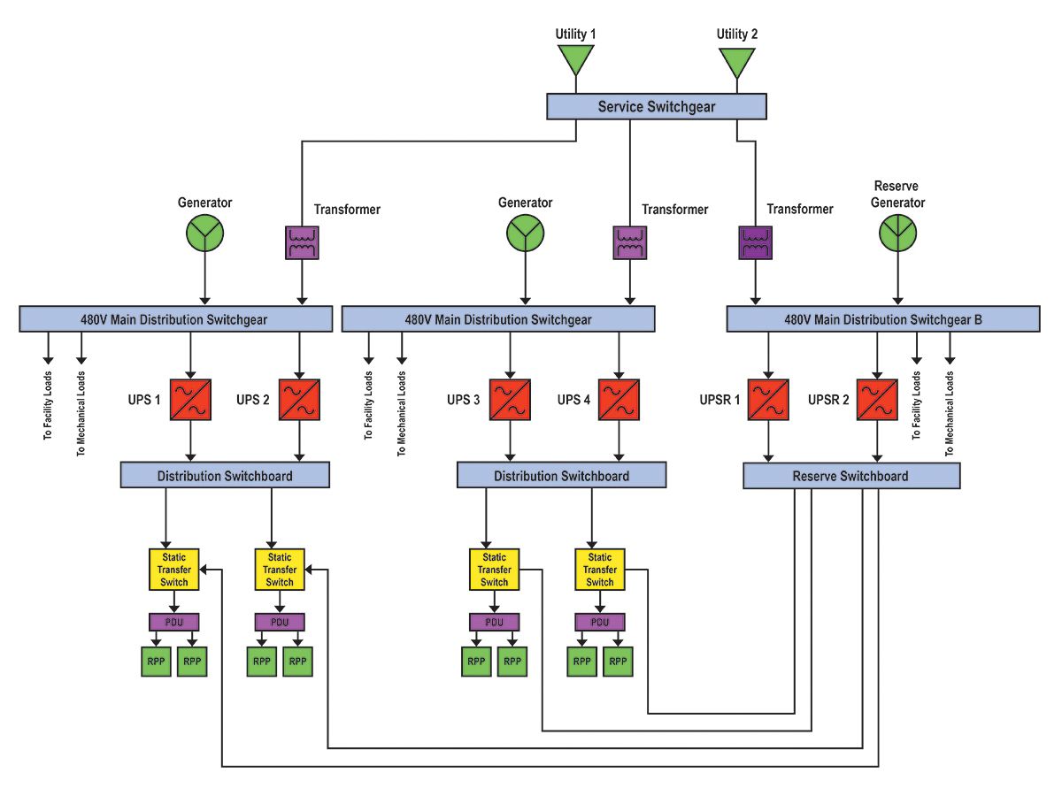
Closely tied to the redundancy requirements is the electrical topology. The two most common types that are used are the distributed redundant and reserve “catcher” schemes, refer to Figure 4 and Figure 5, respectively.
In the distributed redundant system, the critical loads are split nearly evenly between systems. When one system fails, the load it is supporting transfers over to the remaining systems. Note that Figure 4 shows only two transformer generator pairs, but is a 4+1 system based on the failure transfers at the static transfer switches. The key advantages to this topology are that equipment is highly used during normal operating conditions and when one system fails, the load transfers are distributed to multiple systems.
For example, assuming that the systems in Figure 4 are fully loaded, the typical load for all five systems will be 80%. However, distributed redundant systems are difficult to expand once they are installed and require careful load tracking by operations. It is easy to assign loads on a distributed redundant system where the overall system is properly loaded, but a single system failure could result in a point overload in the system.
To overcome the shortfalls of the distributed redundant system, many co-location owners have adopted some form of the catcher system, as shown in Figure 5. In this system, the reserve system is normally unloaded and is waiting to accept load from any single failed system. The system in Figure 5 is a 2+1 system for simplicity, but many co-location operators are increasing N to 6 or higher; i.e., 6+1 to maximize the overall use of their equipment. It is relatively easy to increase the value of N in catcher systems; i.e., expansion from a 4+1 system to 5+1. The only additional equipment required is sufficient reserve breakers and the transformer, generator, and low-voltage distribution.
Co-location facility design is rapidly changing as new technology enters the marketplace and as co-location providers work to trim excess equipment out of their designs to lower their cost structure. Designs that were considered standard just a few years ago are continuing to evolve with the changing marketplace. The designs will continue to change, but understanding the fundamental design principles required to complete a basic co-location design will allow the design engineer to adapt to the market.
Power-usage effectiveness (PUE) is still not uniformly applied and referenced consistently across all clients and data centers. If you are provided a PUE number, ask to have the calculation methodology explained to you. For assistance in understanding this metric, please refer to the Green Grid’s White Paper #49, PUE: A Comprehensive Examination of the Metric.
Target power–usage effectiveness (PUE)
PUE is the ratio of the total energy consumed at the co-location over the energy delivered to the servers including power conditioning. In an ideal world, a co-location would have a PUE of 1.0—i.e., 100% of the power would be used to power the IT load. Understanding both the peak and average PUE projected for the facility is critical in determining the final medium- and low-voltage design. The client will give you the IT load, so the majority of the remaining load will be in the mechanical systems.
PUE can be complicated to calculate for co-location facilities and will determine the location of metering. In particular, UPS, cooling, and other facility systems that are shared between clients complicate the metering and the calculation. Submetering may be required for many systems. PUE is used as a metric by both the co-location’s owner and clients, so it is important to ask at the beginning of design where PUE will be measured and how it will be reported.
Some co-location owners will refer to both peak and average PUE numbers, but if possible, avoid using these terms and just use PUE. Note that systems must be sized to the “peak PUE,” so discussions of average PUE are largely marketing language. These two numbers may be very close to each other if the same mechanical cooling method is used throughout the year. However, if the climate allows for free cooling for the majority of the year but relies on other cooling methods during times of high temperature and humidity, the average may be considerably lower than the peak. PUE values vary considerably, ranging from close to 1.1 to 1.8 in some locations. Co-location PUEs are generally lower than those for owner-operated data centers.
Read more about PUE online at www.csemag.com.
Brian P. Martin, PE, Jacobs, Portland, Ore.
Author Bio: Brian P. Martin is a senior electrical technologist in the advanced facilities—electronics department at Jacobs. He is a member of the Consulting-Specifying Engineer editorial advisory board.