The first ac-power transmission line was built in 1886 in Cerchi, Italy, which transmitted for 17 miles at 2,000 V. To avoid the high cost of conductors needed to transmit high current and the losses associated with high current flow, higher voltage transmission lines were developed. In 1936, a 287-kV transmission line was put in place in the U.S.: The Hoover Dam to Los Angeles line. Currently in the United States, voltages as high as 345 kV are commonly used for transmitting power. Using higher voltages is possible, but careful analyses are done on the economics because the price of the equipment increases substantially when going to a higher voltage level.
Voltage Levels
There are several reasons to choose one voltage level over another for electrical transmission. A major reason is the cost. With higher voltage comes less copper for wiring, but more money for electrical equipment—it's a balancing act. Another reason is the length of the lines. For longer power lines, it makes sense to use higher voltages, but that comes with greater wire spacing. Often, the decision is affected by the existing transmission lines in the specific area. Using the same voltage system makes it easier to interconnect different lines into a grid, and that could make a certain voltage level very attractive, even if immediate costs are higher.
Voltage levels have been standardized so that manufacturers can concentrate on developing certain types of equipment. ANSI C84.1 defines medium voltage (MV) as being "a class of nominal system voltages greater than 1,000 V and less than 100 kV." IEEE 141 (the Red Book) references ANSI C84.1 in recognizing the same voltage levels associated with the MV range. Of all the possibilities of voltage levels between 1 kV and 100 kV, the standard voltages most often used in the United States are 4,160 V, 12,470 V, 13,200 V, 13,800 V, 24,940 V, and 34,500 V for four-wire systems and 69,000 V for three-wire systems. Other voltage systems also are used, such as 2,400 V, 4,800 V, 6,900 V, 8,320 V, 12,000 V, 20,780 V, 22,860 V, 23,000 V, and 46,000 V. Certain voltages, such as 4.1 kV, 6.9 kV, and 13.8 kV, coincide with standard motor voltages, therefore, they are preferred.
Depending on the size of the campus, the end user will have to choose what level of voltage to distribute the power. When choosing the level of voltage, several decisions must be made. Besides the cost of the project, one of the most important aspects is safety. Years ago, electricians routinely worked on energized equipment, and not only low-voltage (LV; 1,000 V or less) equipment but also on MV equipment. This practice has been very much limited because it is very dangerous. Where maintenance activity is still performed on energized gear, safety is the primary concern. To address safety, NFPA: National Electrical Code (NEC) Article 110: Requirements for Electrical Installations, requires certain working space clearances around the electrical equipment—the higher the nominal voltage, the greater the required clearance. Equipment maintenance is another factor when deciding the electrical system voltage level. If the maintenance team is already trained in certain voltage-type equipment, it makes sense to continue using that same voltage level. Otherwise, additional training will be necessary.
Using an MV distribution system has several advantages as compared with LV distribution. Voltage and current have an inverse relationship. Given a certain demand for power, the higher the voltage, the lower the current, based on the equation:
P = V x I
Where P = power, V = voltage, and I = current.
Sometimes the distance is not the issue, but rather, the amount of power to be distributed. Residential buildings do not have a great need for power, so the use of LV suits them well. But commercial clients routinely ask for great amounts of power. Assume that a certain client needs 10 MW of power (or 12 MVA). If distributing this power at LV (480 V, for example), the facility would need to accommodate almost 14,450 amps. That's an enormous amount of current, which requires an enormous amount of wiring. In comparison, the same 12 MVA would only produce about 500 amps at 13.8 kV. This lower-current solution gives the owner the flexibility of delivering the power through the building as close to the load as possible and then stepping the power down to LV for consumption. Choosing to distribute the electrical power via MV also helps minimize power losses, which adds to operation savings.The inverse is true as well: the lower the voltage, the higher the current. The MV system delivers the same power quantity via a smaller amount of current in comparison with LV. A lower amount of current affords smaller conductors and/or fewer sets of conductors to distribute the power, which results in significant savings. Lower current levels also result in lower power losses, and as a consequence, lower voltage drop. Lower voltage drop makes power distribution to greater distances possible. It is very common for a campus arrangement to have a 13.8-kV distribution system with the voltage step-down to 480 V at the building and 4,160 V and 480 V at the central utility building. If the distances from the main utility substation of the campus to the individual buildings are great, higher voltages could be used, but the 13.8-kV distribution system is very common. Other common voltages are 12.47 kV, 24 kV, and 24.9 kV (nominally 25 kV).
Designing a Distribution System
When designing an MV distribution system, special attention must be given to equipment dimensions, ratings, and their clearances. The equipment dimensions are greater for MV systems as compared with LV systems. Therefore, space dedicated to equipment becomes very important and should be allocated early in the design process. Table 1 shows a comparison of the electrical equipment for two very common voltage systems, 480 V and 13.8 kV, using the same equipment manufacturer.
The working clearances around the MV equipment are also greater than the clearances of the LV equipment. NEC Article 110 describes the minimum working clearances around the electrical equipment. Table 2 compares the working clearances for the same two distribution systems as those listed in Table 1.
Condition 1 is satisfied when there is an exposed live part on one side but no live or grounded parts on the opposite side of the working space. If there are live parts on both sides, Condition 1 is satisfied only if the parts are guarded by insulating materials. Condition 2 applies when there are exposed live parts on one side of the working space and grounded parts on the other, with concrete, brick, and tile considered to be grounded. Condition 3 is the worst-case scenario with exposed live parts on both sides of the working space.
If the MV equipment is outdoors, it should at least be confined by a fence, which, depending on the voltage level, should be a minimum of 10 feet away from live parts or the enclosure. For a nominal 13.8-kV system, the clearance should be 15 feet. Refer to NEC Article 110.31 for further details.
MV equipment does not have the same flexibility as LV equipment. For LV systems, there are circuit breakers of all sizes, and larger breakers are equipped with easily adjustable trip units. For simple MV systems, fused switches can be used for protection, and these fuses come in many sizes as well. However, in complex MV distribution systems, such as in mission critical facilities, using MV breakers becomes a necessity. The smallest circuit breaker for a nominal 13.8-kV system (15-kV switchgear) is rated at 1,200 amps. The next size up is 2,000 amps, then 3,000 amps. As previously mentioned, the great advantage of MV systems is that the current is low, but there is currently no breaker small enough for these systems. However, there are 630-amp breakers available for International Electrotechnical Commission (IEC) systems. This circuit breaker is what we call a "dumb" breaker. It is called dumb because it is not equipped with any intelligence, and it does not know when to clear a fault. For that reason, relays are used. Relays offer excellent protection capabilities and schemes, but that does not take away the fact that the smallest MV circuit breaker, at 1,200 amp, is very often too large for the amount of current that goes through. This lack of flexibility has financial implications that must be considered.
Fault protection for MV systems becomes important because of the implications of a protection failure. A 1,200-amp circuit breaker rated at 480 V could carry close to 1 MVA worth of power (if 100-rated and loaded). In comparison, a 1,200-amp circuit breaker at 13.8 kV could carry more than 28 MVA. As we can see, the MV breaker supplies a much larger load, thus, it is crucial that protection is provided. Because of this great impact on the distribution system from a single failure, reliability of the system becomes an important piece of the design effort. IEEE 493-2007: Industrial Power Systems Design (the Gold Book) is a good resource for reliability analysis. Based on these analyses and the owner's needs, redundancy could be built into the system. The redundancy can be N + x (where x could be 1, 2, or any number) or 2N. A 2N system requires two sources of power for each piece of equipment, with each source being fully capable of carrying the entire load (see Figure 1). In case of a fault in the "A" side, the power is still available via the "B" side. When side A is unavailable, the system is not 2N until side A is brought back into service. Redundancy is important to consider at any voltage level, but it becomes especially important in MV systems because large amounts of power are provided and could be lost. Using the same example, the 1,200-amp breaker at 480 V could carry close to 1 MVA, and at 13.8 kV could carry more than 28 MVA. Losing 28 MVA could have a much greater effect than losing 1 MVA of power.
For large and complex electrical systems, protection for an MV system easily can be designed using relays, but it can get complicated and must be thought out carefully. There are many kinds of protection schemes, and usually a robust system has many different relay types and functionalities engaged. Each relay type has a dedicated number, as does every protection device, depicted in ANSI/IEEE C37.2, which makes it easier to design and also understand other peoples' designs. A differential protection relay (87) sums the incoming currents and compares them with the sum of the outgoing currents. This kind of protection is among the most common because it is fast-acting. Differential protection is applied to the main bus for the equipment and the zone that encompasses all the breakers. Differential protection can also be provided for MV transformers and feeders that are of significant length. Other common types of protection are overcurrent (51), instantaneous (50), overvoltage (59), undervoltage (27), reverse power (32), and many more. An excellent source on protection of electrical systems is IEEE 242-2001: Protection and Coordination of Industrial and Commercial Power Systems.
In the last decade, there have been efforts to centralize the protection of MV gear. Separate relays send signals to a central device, which then processes the information and decides what action, if any, should take place to avoid nuisance tripping. The signal can be sent back and forth via fiber wiring or wirelessly. This technology was developed first in Europe, and the standard covering it is IEC 61850: Power Utility Automation. This technology is promising, but has yet to be widely used.
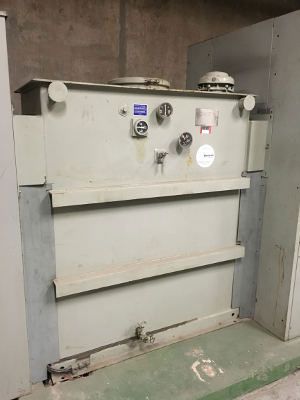
MV distribution transformers also tend to be larger and more expensive than LV transformers. Because of the impact that a transformer malfunction could have for the entire system, there is more emphasis on protecting MV transformers. In addition to the usual overcurrent protection that LV transformers could receive, MV transformers receive a thermal relay (49) to monitor oil temperature, a pressure switch (63) to monitor the pressure in the oil tank, and a liquid level switch (71) to monitor the oil level (see Figure 2). All of these relays would trip the breaker for a preset value of respective parameters that are out of acceptable ranges. To clarify, some LV transformers could get all these levels of protection—but in MV transformers, such protection is routine.
Backup Power
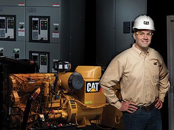
MV distribution systems offer the same advantages as the utility side on the backup (or standby) power side as well. A 13.8-kV system, for example, can be backed up by 13.8-kV generators. The backup power produced by the generators can be just as easily distributed as close to the load as possible, like the utility side. Depending on the type of distribution system design, often there is the need to parallel these MV generators to back up the entire system.
There are several issues to consider when paralleling MV generators. One is reliability. For example, if there are four generators needed to support the power system in case of total utility failure, the next decision is the scale of redundancy. If N + 1 is required, we would need to employ five generators with four out of five needed at any given time. The reliability (availability) of such a system is 0.999. If less reliability is acceptable, only four generators could be used for an availability of 0.96. For details on how to calculate the reliability of power systems, refer to IEEE Gold Book.
Another decision is how the backup system interacts with the utility. In many cases, an open transition—where the backup system is disconnected from the load before the utility power is connected back into it—is sufficient. Open transitions are easier and simpler to implement. In some cases, closed transition is required—where the backup power system and utility power system are paralleled for a very short period of time, typically a few cycles.
Examples of closed-transition systems can be found in hospitals and data centers. Closed transition adds complexity to the distribution system because the controls and relaying would have to include more zones of control.
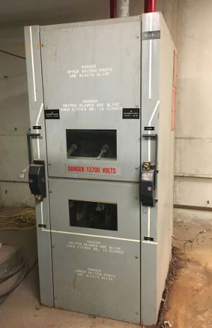
Also, because of paralleling between the utility and standby power, the short-circuit current availability increases the worst-case scenario of a fault happening at the time of the closed transition. This increase in fault duty could push the switchgear rating to the next higher standard rating, which could impact costs significantly (see Figure 3).
An MV system backed up by standby generators also requires close attention to grounding and ground fault protection. Grounding of electrical systems is a broad topic and will not be addressed here, except to direct the reader to two good resources: IEEE 142-1991: Grounding of Industrial and Commercial Power Systems, and IEEE C37.101: Guide for Generator Ground Protection.
MV Pros and Cons
MV distribution systems have many advantages over LV distributions, but they also have some disadvantages. The choice must be the result of careful analysis, where cost and safety are the prevailing factors. Advantages of MV systems include the use of much less copper in the form of smaller conductors and fewer sets of conductors, fewer power losses, lower voltage drop, and, as a result, distribution of much more power capacity to the load. Disadvantages of MV systems include larger equipment sizes, greater working clearances required around the electrical equipment, more investments in training, and longer maintenance periods to repair equipment.
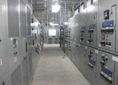
Regardless of these advantages and disadvantages, sometimes distributing at LV is not possible, in which case MV distribution is used (see Figure 4). In such cases, careful consideration should be given to the safety of workers by developing detailed procedures on how to maintain the MV equipment. Safety of nonmaintenance personnel also should be considered carefully. The most effective way to ensure safety is to lock the doors of areas where MV equipment is housed and to not allow entrance of unauthorized personnel.


