Overcurrent More than 800 Amps
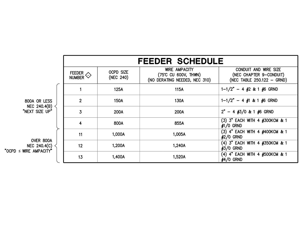
NEC 240.4(C) outlines the use of current-limiting OCPDs over 800 amps and is more prescriptive than NEC 240.4(B). This code section states that the OCPD must be of equal or greater ampacity to the conductors being protected. With an OCPD larger than 800 amps, the designer is typically sizing a distribution board feeder or large transformer.
Example (assuming the same conditions as the previous example and that no derating need occur for wiring inside the building):
Load:
- (Two) panelboards
- Panelboard 1: 250 kVA N Code and 20 kVA of L Code
- Panelboard 2: 400 kVA N Code and 100 kVA of L Code
- Total = 120 kVA x 1.25 + 650 kVA = 800 kVA
- Current = 800 kVA at 480 V/3-phase = 963 amps
- Wire ampacity: #400 KCM is rated for 335 amps; running (three) parallel sets allows a wire ampacity of 1,005 amps
- OCPD that is equal or less than ampacity: 1,000 amps
- 1,000 amps: (three) 4 in—each with four #400 KCM and one #1/0 Ground (refer to Figure 1 for more examples).
Transformers
Transformer circuit protection is outlined within NEC 450, specifically 450.3. A typical commercial facility will have utilization voltages of 120/208 V and 277/480 V with an indoor transformer; these voltages will use NEC Table 450.3(B) for transformer OCPDs of 1,000 V or less.
There are two distinct configurations of circuit protection for transformers: primary-only protection or primary and secondary protection. These requirements are outlined in NEC 240.21. Primary-only protection is outlined within NEC 240.21(C)(1) and is allowed for some single-phase or multiphase delta-delta connected transformers. More commonly, primary and secondary protection is required for the transformer. For these requirements, NEC 240.21(C) shall apply for different scenarios depending on the length of the secondary conductors.
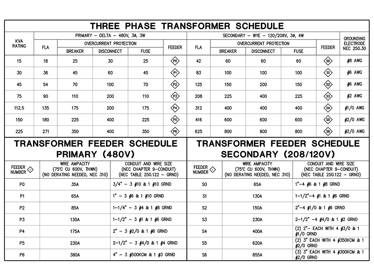
For example, a facility is equipped with a 75-kVA transformer with a 480 V, 3-phase, 3-wire primary and 120/208V, 3-phase, 4-wire secondary. The transformer is indoors with a secondary feeder that is 15 ft long, thus it is required to have primary and secondary protection (NEC 240.4(F), 240.21(C)(6)).
Primary full load amps (FLA): 75,000 VA/480 V x 1.73 = 90.3 amps
- FLA x 2.5 = 225.8
- Primary OCPD: up to 250% of FLA, up to 225 amps per NEC Table 450.3(B), recommended 125 amps
Secondary FLA: 75,000 VA/208 V x 1.73 = 208.4 amps
- FLA x 1.25 = 260.5
- Secondary OCPD: up to 125% of FLA, up to 275 amps per NEC Table 450.3(B), recommended 225 amps
A few notes: 125 amps is recommended as the primary OCPD; however, this OCPD should be plotted against the transformer inrush current because a lower size could result in nuisance tripping of the primary OCPD. In addition, the secondary OCPD should be coordinated against any high inrush loads to ensure nuisance tripping from the load does not occur.
Outdoor installations and installations of more than 1,000 V were not covered but are outlined within NEC 450. See Figure 2.
Ground-fault Circuit Protection
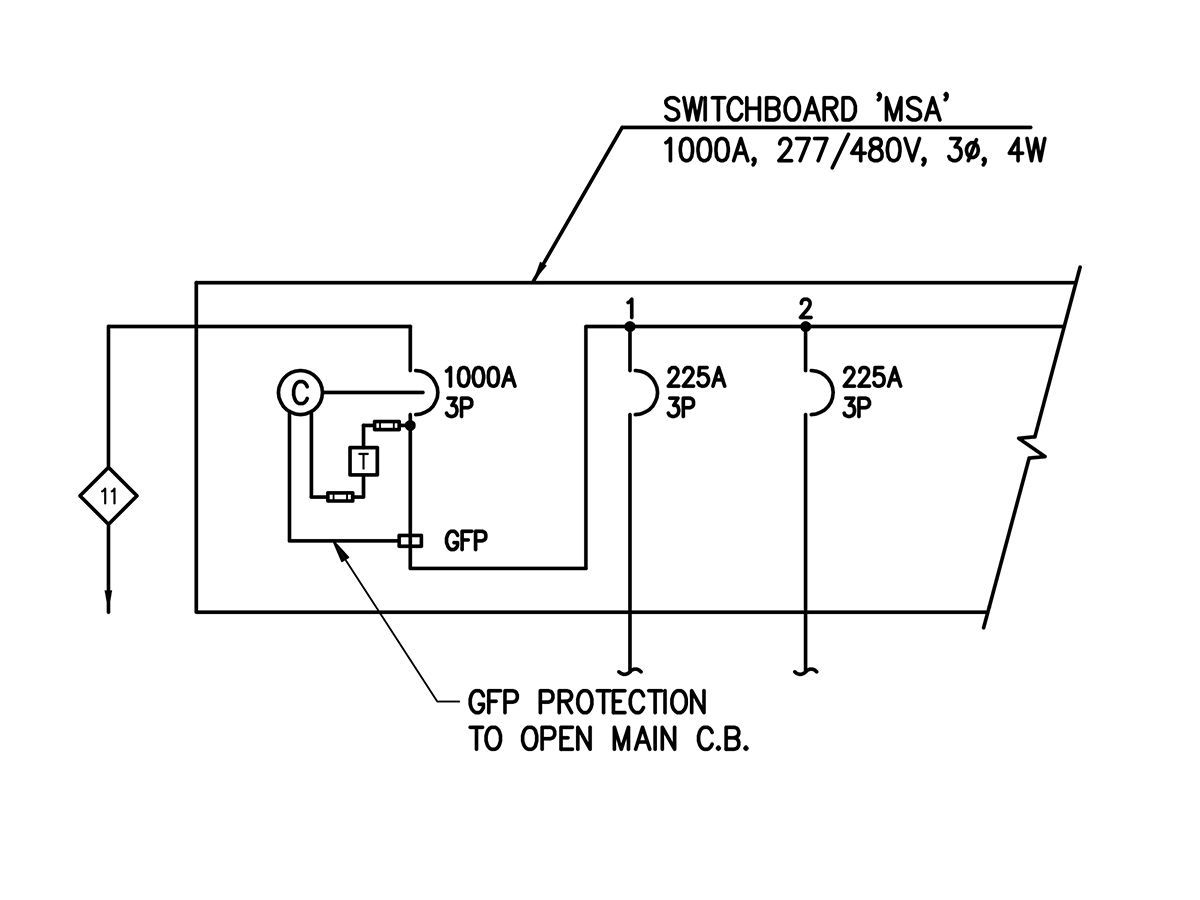
Ground-fault protection is another common circuit-protection scheme. Individual line-to-ground faults are generally understood to be among the most common fault types. The main goal of ground-fault protection is to disconnect the circuit in the event of a line-to-ground fault. The protection would then open or clear all ungrounded conductors to clear the fault from the system. There are two different levels of ground-fault protection. Ground-fault circuit protection for personnel ranges from 4 to 6 mA and is referred to as a ground-fault circuit interrupter (GFCI). Ground-fault protection of equipment has a higher protection of 30 mA. The most common example of personnel protection is seen in most occupancies and is typically within 6 feet of standing water, which is a standard GFCI-type receptacle and primarily governed by NEC 210.8. The higher-rated equipment protection is commonly used for protection of services, electric heating elements, equipment, or large feeders; it is primarily outlined in NEC 210.13 and 230.95 for solidly grounded wye systems that are more than 150 V to ground and less than 1,000 V phase to phase and at or more than 1,000 amps. The primary objective of this type of protection is the load-side conductors and equipment that are downstream of the 1,000 amps or higher disconnect. The requirement of ground fault equipment protection (GFEP or GFP) in service feeders is to clear lower-level ground faults on these services. A typical ground fault in these systems will not be detected by a higher-ampacity breaker because these faults can be substantially less than 1,000 amps and still be damaging. In addition, GFEP is a necessity for fixed outdoor snow-melt equipment (NEC 426.28) and for heat trace (NEC 427.22).
The easiest way to include GFEP would be to add a neutral sensing circuit to the main breaker, which would compare this neutral current against the phase currents to detect an imbalance. In a fused system, the fuses are only inherently capable of clearing high-amperage faults. For lower-level, high-impedance ground faults, the fuse must be supplemented by controls on the switch or contact. This is typically via the addition of relays or sensing circuits that can automatically open the switch.
Arc-fault circuit interrupter (AFCI) protection is gaining quite a bit of traction in recent code cycles and is intended mainly to prevent an arcing-type fault that could result in a fire. AFCI devices are primarily required in dwelling or sleeping quarters. NEC 210.12 governs the application of AFCI-type devices, and the most recent addition to this code section are guest rooms, per NEC 210.12(C). These devices differ from GFCI as they monitor the sine wave electronically and determine if arcs are occurring at predetermined frequencies. If this occurs, the AFCI will open the circuit and eliminate the arcing hazard. AFCI was first introduced into the code in the 1999 NEC code cycle and has continually expanded each year. See Figure 3.
Circuit Protection for Motors
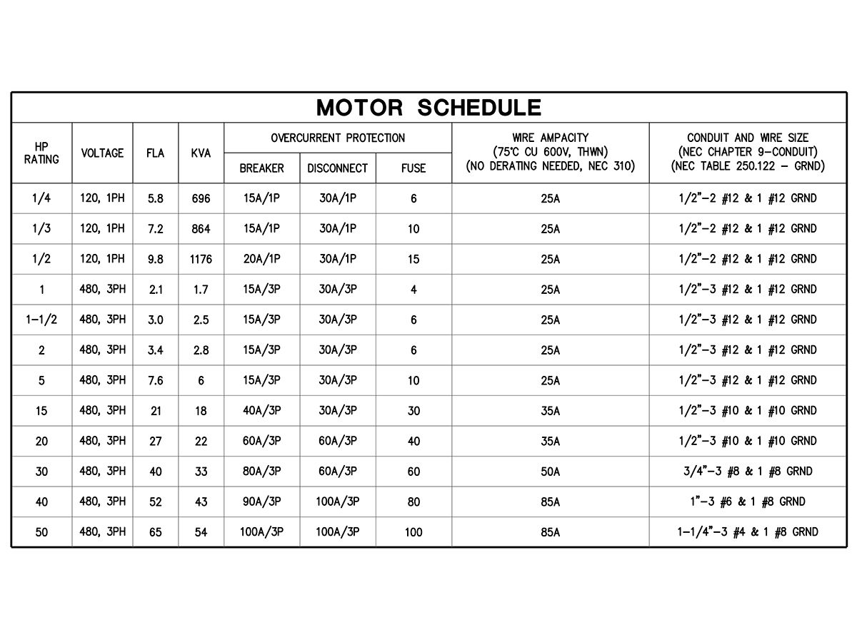
Generally, a motor’s OCPD device is designed to protect the motor from short circuit and ground faults and not the wire/cable from overload. Instead, the motor will be outfitted with an overload device, often built into the controller, which will protect the motor and branch-circuit feeder from excessive heating due to a motor overload or failure to start (NEC 430.31). There are a few exceptions to this, such as cord and plug-connected motors (NEC 430.42(C)). This also prevents the OCPD from nuisance tripping during motor startup.
Example: A building has a ½-hp 120 V, 1-phase fan coil. To properly protect this, we will first refer to NEC Table 430.248 for the FLA, which is found to be 9.8 amps. Referring to NEC Table 430.52, it can be determined that the OCPD as a standard molded-case circuit breaker (MCCB) can be a maximum of 250% of the FLA. In this application, the recommended size is 20 amps, which is the highest standard size under the 250% maximum. It should be noted that it is code-allowable to use a 25-amp MCCB; however, this is not ideal per NEC 430.52(C)(1), Exception No. 2(c). See Figure 4.
Short Circuits in Electrical Distribution Systems
Electrical distribution systems require an in-depth short circuit study to reveal areas that need larger ampere-interrupting-capacity (AIC) ratings for equipment. If this is not coordinated, it can be catastrophic. If a circuit breaker experiences a short circuit that exceeds its AIC rating, the breaker may explode or melt the contacts together and result in a fault not clearing. To circumvent this, the engineer can either fully rate all breakers for the higher interrupting current or series rate the breakers. Applying a series rating is the method of using the upstream protection to clear the short circuit while also preventing downstream damage. This method is typically applied between a main breaker and downstream branch-circuit breakers. For example, a series-rated branch-circuit breaker may be able to be a 10,000 AIC or 10 KAIC (K indicating thousand) circuit breaker with a 22 KAIC main breaker (120/208 Y system), this allows the panel’s main breaker to clear the short-circuit fault while still protecting loads. This also is explored in facilities that have high incoming available faults from the utility, which would like to save costs during the construction phase since higher AIC breakers are often much more expensive. One drawback of this scheme would be that the fault will now de-energize the whole panelboard instead of an individual branch circuit. This clearly violates any degree of selective coordination and may not be applied to emergency systems (NEC 700), legally required systems (NEC 701), health care systems (NEC 517.26), or elevator distribution (NEC 620.16). NEC 240.86 outlines the methods for applying a series rating.
It should be noted that, currently, no computerized program is capable of determining series ratings for circuit breakers, and compatible circuit breakers are only determined via testing. Currently, no major circuit breaker manufacturers are pursuing a UL-series rating with competitors’ devices. As such, the entire system to be series rated must be from the same manufacturer to allow a series rating.
This is a concern to address in a circuit-protection scheme. During design, the engineer should perform a fault calculation for all project feeders, from the utility service down to every panelboard throughout the property. If necessary to meet budgetary constraints, a series rating can be applied. It should be cautioned that the series rating should only be applied after an in-depth short circuit study is conducted during construction, with more accurate feeder lengths, wire types, etc.
In a standard system, it is commonly accepted that preference is given to fully rated equipment and to minimize, if not completely eliminate, series ratings. Inevitably at an existing property or a large property that may experience several expansions and renovations, a few pieces of series-rated equipment may be added. However, series rating equipment restricts future additions and limits future manufacturer choices for equipment, therefore it is generally not recommended.
Minimizing Outages with Selective Coordination
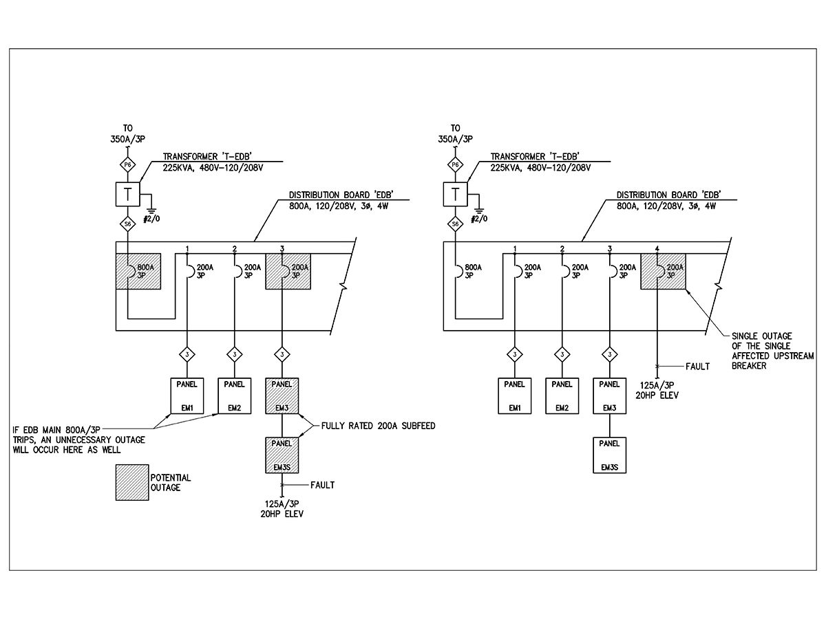
One of the most important concepts in a circuit-protection scheme is minimizing outages to the branch device at which the fault or outage occurred. This is when the concept of selective coordination is applied. In short, selective coordination is the selection of OCPDs in a manner such that the furthest downstream device trips before the upstream OCPD trips. For example, if a fault occurs on an emergency lighting branch circuit, it can carry upstream to a 42-circuit panelboard main OCPD and open this device. Thus, the facility would lose an entire 42-circuit panelboard in lieu of the single branch circuit. Due to this concern, the NEC has developed code to require selective coordination on life safety loads and legally required systems (NEC 700.32, 701.27). Generally, a coordination ratio of 2.5:1 will achieve coordination with most MCCBs while a lower ratio of 2:1 will achieve coordination with most fuses.
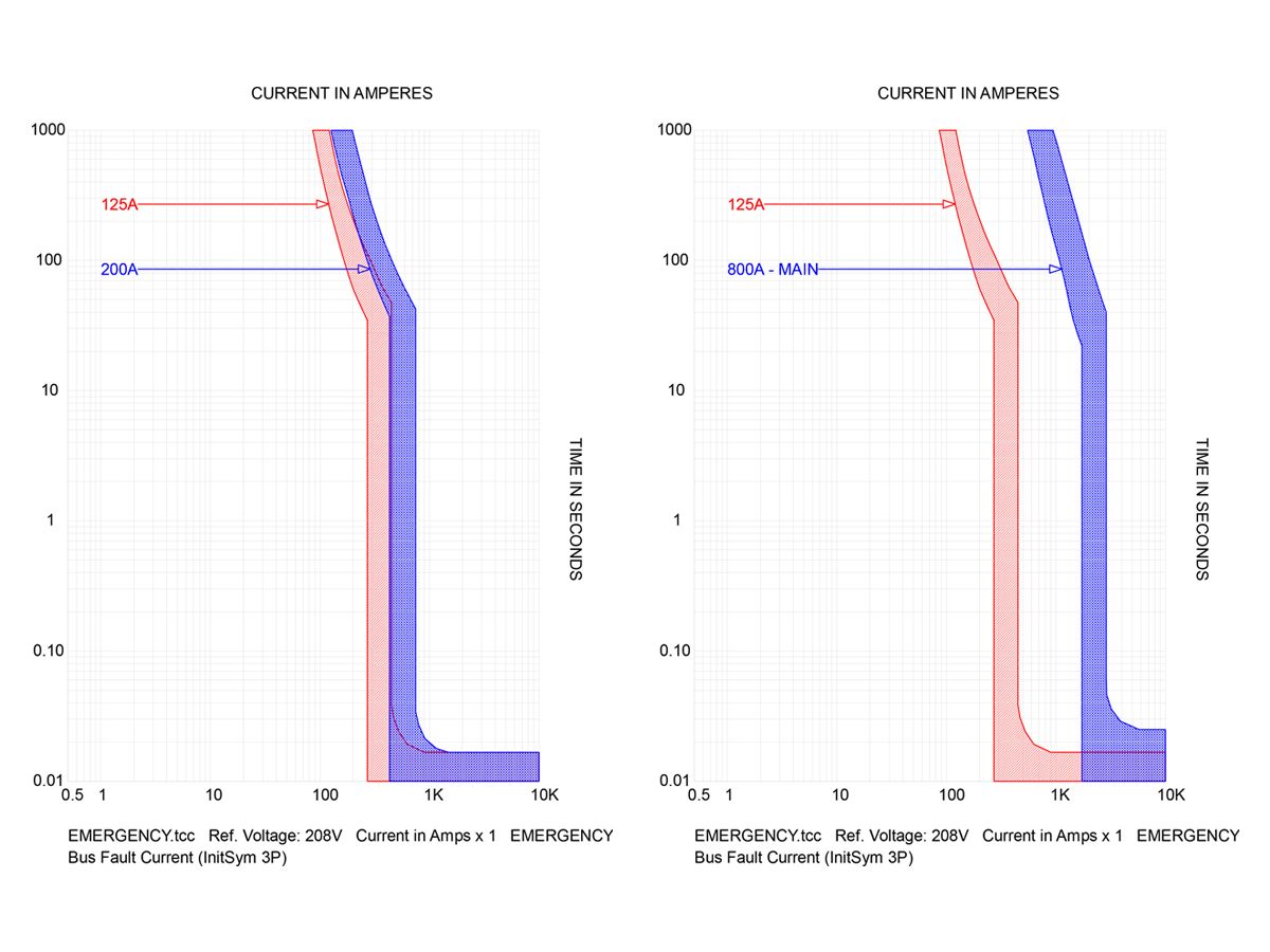
Beyond the above simple ratios, selective-coordination studies are necessary to confirm the coordination of the breakers. This is often rolled into an overall arc flash, selective coordination, and short circuit study. This study will overlay several breakers and their associated time-current curves (TCCs) and determine the level of coordination based on the overlap regions.
A good rule to follow is to use fused coordination panelboards and upstream fuses or adjustable electronic trip circuit breakers for NEC 700 and 701 systems. This will allow an easier degree of coordination and, using the above-mentioned ratios, most selective-coordination issues should be resolved. Of course, every project presents a new set of problems and must be analyzed in a full-coordination study for verification.
It should be noted that the NEC requires a full degree of coordination, which implies that coordination must be taken from time zero. However, manufacturers cannot publish results at time zero, thus 0.01 seconds is an accepted time for a low range of a TCC. See Figure 5, 5a, and 5b.
Arc Flash Hazards
Nearly every piece of electrical equipment will at one time be inspected or worked on in some form. It is recommended that any service be performed on de-energized equipment, but there are instances where a scheduled outage is not feasible. In these instances, the licensed electrician is exposed to many hazards. Arc flash is one such hazard and a significant risk to human life and electrical infrastructure.
The risk of arc flash is created by a combination of three issues: available fault, working distance/clearance, and clearing time of the device. While designing a circuit-protection scheme, the main item within the designer’s direct control is the clearing time of the device. The available fault is a function of the utility service and impedances of the system’s transformers. Although this can be controlled during the design process, it is often an inefficient way to handle arc flash. Next, the working distance will continue to be a fixed approach distance, as the technician will need to physically be close enough to complete the required work. This leaves the device clearing time for the designer to handle. The 2017 edition of the NEC recognizes this and includes the requirement for the clearing time to be incorporated into the arc-flash labeling of service equipment, per NEC 110.16(B)(3).
During the design process, reducing the clearing time to a minimized level will be directly contrary to selective coordination. These two concepts are essentially at odds with one another. For this reason, one of the most common solutions for arc flash reduction, which is required by NEC 240.87 for trip settings of 1,200 amps or higher, is the use of a maintenance switch on the equipment. This allows the electrician to turn on a more sensitive level of protection at the equipment (quicker trip settings on electronically controlled OCPDs). It will effectively result in a miscoordination upstream; however, while the electrician is working, the largest concern is the preservation of human life and not a system outage. After the required work is complete, the electrician will then set the maintenance switch to “off,” which will restore the previously coordinated settings. There is no one single solution for arc-flash energy reduction, and it is often prudent to incorporate as many protections as possible. Another protection scheme is the use of arc-resistant switchgear. By definition, arc-resistant switchgear mitigates the hazards of arc flash through reinforced bracing and by providing discharge paths for arc-blast pressure. However, arc-resistant switchgear will typically need to be opened for most work to take place, thus this would negate many benefits of the switchgear.
Another solution to comply with NEC 240.87 is zone-selective interlocking (ZSI). ZSI is the use of electronically adjustable circuit breakers to clear a fault quickly while maintaining selective coordination. ZSI works with a set of networked electronic breakers. When a fault condition is detected, the breaker that is closest to the fault sends a blocking signal to any other breakers to keep their preset trip settings while the closest breaker overrides the preset short time setting and trips with no delay. This will clear the fault as quickly as possible while maintaining coordination. Also, by sending a blocking signal in which the upstream breaker maintains the preset trip settings, the upstream breaker will still be available to open in the event of the downstream breaker fails to clear the fault.
Protective Relaying
Relay protection is an added layer of protection that can range from simple single-point protection to complicated zonal protection. Protective relaying schemes are usually seen on large campus-style distribution, paralleling switchgear, generator feeders, and other complicated systems. Protective relaying in its simplest form is the use of an external sensing relay that will then activate the breaker or switch to open or clear the faulted condition that the relay has sensed. These devices use the same functionality of the previously mentioned dedicated devices; however, they use a microprocessor to then provide the functionality of multiple devices and are capable of being customized for specific site conditions and anomalies.
There are many levels of protection that are outlined by the ANSI/IEEE C37.2-2008 Standard Electrical Power System Device Function Numbers, Acronyms, and Contact Designations (2008). The functions of the OCPD or relay are characterized by a number, for example, 87 indicates differential relay, 27 is for undervoltage, 67 is for ac directional overcurrent, etc. These devices may be used to implement any of the protection schemes in this article and myriad other designs. They are a supplement to the aforementioned dedicated devices and should always remain a consideration on devices that require multiple levels of protection.
Stephen Berta is a project consultant at NV5. He has experience in education, hospitality, gaming, and data center projects.


