Facility Guidelines Institute's (FGI) Guidelines for Design and Construction of Hospital and Health Care Facilities: This publication is a helpful tool and widely used by design professionals (architects, planners, engineers, and consultants) to not only improve the quality of health care design, but also to follow the minimum standards set for the new facilities and major renovations in terms of planning, design, construction, and commissioning. The guidelines are used either as a code or a reference standard by the Joint Commission, and federal and state officials/agencies throughout the U.S. with the exception of a few states. There are specific sections in the guidelines that address the requirements for the building systems for each type of facility that are very helpful. The electrical section addresses specific requirements related to lighting and illumination levels, materials and equipment, testing and documentation, emergency generating and storage, receptacles, etc.
EES branches
The EES for hospitals shall consist of separate branches to allow sequential transfer of power from the normal source to an alternate source for blocks of loads in order of priority and critical nature of the loads. The NEC Article 517 requirements are consistent with NFPA 99 for EES Type 1, and is comprised of three separate branches (life safety, critical, and equipment). However, EES Type 2, which is comprised of two separate branches (life safety and equipment), is only mentioned in NFPA 99. The Category 2 spaces are allowed to be served by an EES Type 1 that is serving the Category 1 spaces in the same facility. In general, there are very few differences between EES Type 1 and Type 2, with the exception of critical power and how the power is distributed throughout the facility.
The life safety and critical branches shall be kept independent of all other wiring and equipment. The wiring of the life safety and critical branches shall be mechanically protected by raceways, as defined in NEC.
The life safety- and critical-branch loads shall be installed and connected to the alternate source of power in a manner that power is automatically restored to these loads within 10 sec of power interruption. The equipment-branch loads shall be installed and connected to the alternate source of power at appropriate time-lag intervals after power interruption via delayed automatic or manual connection as prescribed by code.
Life safety branch: The life safety branch of the EES provides power to those functions or warning systems that are required to allow building occupants to safely leave the building in an emergency. The life safety branch is limited to only selected functions connected to it, including illumination of means of egress, exit signs, fire alarm, medical-gas alarms, communications, selected loads related to the generator and transfer switch locations, and automatic doors used for building egress. The full description of what is allowed is listed in NEC 517.32.
Critical Branch: The critical branch is intended to serve a limited amount of loads that either have immediate impact on the well-being of patients or are essential to the clinical functionality of the health care facility itself. The critical branch shall supply power for task illumination, fixed equipment, select receptacles, and special power circuits serving functions related to patient care. Functions and spaces requiring critical-branch receptacles and lighting include anesthetizing locations (operating and procedure rooms), nurseries, patient bedrooms, angio and cardiac catheterization labs, nurse-call systems and nurse stations, medication preparation and pharmacy, communications systems, and additional specialized patient care areas. The full list of functions and spaces is defined in NEC 517.33.
Equipment branch: The equipment branch essentially serves the mechanical loads required for the support of clinical activities. The loads associated with this branch consist predominantly of multiphase equipment such as motors, compressors, pumps, and fans that introduce high-inrush currents during operation. They shall be arranged for automatic delayed transfer to EES in a manner to allow sequential start to avoid tripping of overcurrent protective devices (OCPD) and overloading generators.
Equipment typically connected include HVAC (ventilation, exhaust/smoke control, and stair-pressurization systems), medical air and vacuum pumps, and other systems that support patient/clinical functions. The full list of equipment to be connected can be found in NEC 517.34.
Sources of power
The EES loads shall be served by at least two independent sources of power, and one of the sources shall be located on site. The normal source, which is generally the public utility-supplied source, shall be sized to serve the entire electrical system along with a single or multiple alternate sources for use when the normal source of power is interrupted.
Normal source of power: Dual-source-of-utility service shall be considered to provide higher levels of service continuity and reliability. The multiple independent services that are provided from different utility substations or sources shall be properly interlocked and protected per utility-company requirements to prevent paralleling of utility feeders.
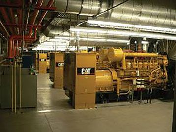
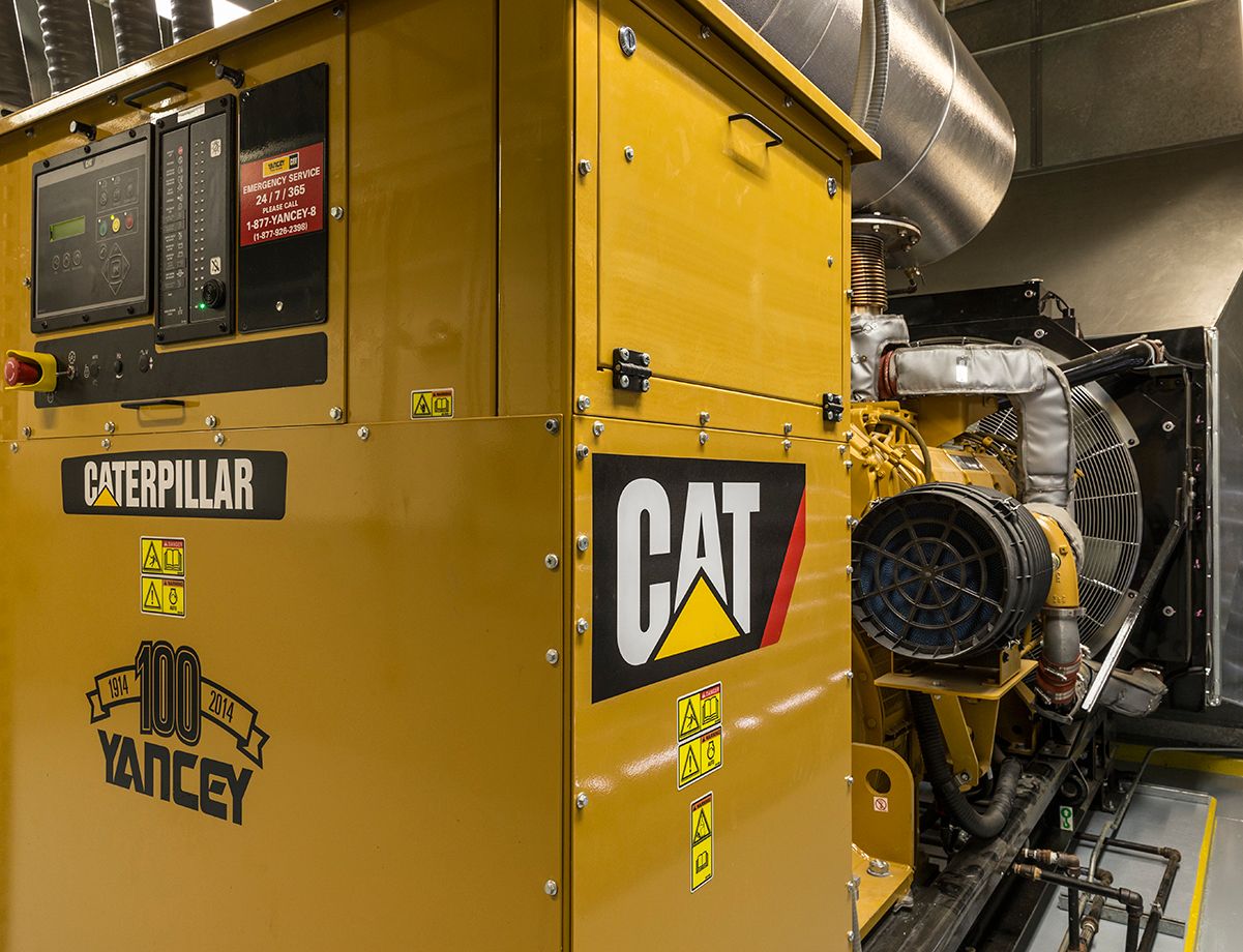
Alternate source of power: The alternate source of power shall be a generator driven by some form of prime movers and located on site. The location of generators shall be carefully coordinated to maintain proper separation between incoming utility-service equipment and generators to ensure the failure of one source will not impact the other. It also is recommended to keep the generators as far away as possible from outside air intake and air conditioning units to avoid drawing generator exhaust inside the building and to minimize exposure to high levels of noise. Generator exhaust and noise are serious issues that should be addressed carefully on every project, particularly for the projects near residential neighborhoods.
Unfortunately, the requirements stated for the fuel capacity and generator run time are not consistent between the relevant codes and standards. Many states and local jurisdictions have their own specific requirements that should be followed when they exceed the minimum fuel capacities listed in the following codes/standards:
- NFPA 70 Article 700.12(B)(2) requires a minimum fuel supply of 2 hr for operation of the system at full demand.
- NFPA 101 requires a minimum of 1.5 hr for illumination of means of egress and exit signs.
- NFPA 99 does not specify fuel capacity and generator run time, but requires an alarm notification when the fuel supply in the main tank drops below 4 hr.
- NFPA 110 requires different run times for the EPSSs based on the classification of them. According to NFPA 99, both Type 1 and Type 2 EES power sources in hospitals shall be classified as "Type 10, Class X, Level 1" generator sets per NFPA 110. Class X classification does not specify fuel capacity required and defers the decision to the local authorities having jurisdiction (AHJ). The typical fuel-capacity hours required by AHJ range from 24 to 96 hr, depending on the location and potential hazards.
- FGI's Guidelines, section 2.1-8.3.3.1(2), requires a minimum fuel supply of 24 hr to allow continuous operation. The appendix A2.1-8.3.3.1(2) recommends a storage capacity of 96 hr for facilities in areas that are likely to experience extended power outages.
According to NFPA 99-2015, fuel cell systems are considered acceptable alternate sources of power and shall be permitted to serve all or part of the EES provided certain conditions are met. This will enable hospitals to greatly benefit from generating their own power to not only reduce their utility bill, but also reduce the size of their generator(s) with an active backup system that could be used during normal power outages.
Fuel cells in certain parts of the country may prove to be a cost-effective addition to hospitals and other facilities in which power reliability is critical, and where the cost of electricity is high relative to natural gas, propane, or diesel.
Generators, paralleling, and distribution equipment
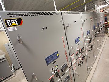
For larger hospitals or campus environments, it is highly recommended to use multiple generators controlled by paralleling switchgear with intelligence (supervisory control and data acquisition and programmable logic controller). This will not only improve the reliability of the alternate source of power, but also provide flexibility to add or shed loads as required, among many other benefits.
A single generator may not be able to sufficiently handle the total capacity of life safety and critical loads in larger facilities. Consideration should be given to design a multiple-bus arrangement to isolate the load breakers from generators; or simply use a split-bus paralleling switchgear arrangement to allow simultaneous start of two generators that could be up and running within the 10-sec time constraint while connected to the separate buses. Once the generators are synchronized, they can then be connected via a tie breaker.
The electrical distribution systems for hospitals, due to size, application of different codes, continuously changing technologies and components, are often very complex and require considerable coordination for the various subsystems involved. Design of EES is one of the key elements of the electrical distribution system because it is required to perform under any circumstances without disruption. To keep the EES functioning properly, special attention is required for the overcurrent-device coordination of the entire system. This is particularly important for the portion of the system serving the most vulnerable loads: the life safety and critical-branch distribution equipment.
According to NFPA 99, the OCPDs serving the essential electrical system shall selectively coordinate for the period of time that a fault's duration extends beyond 0.1 sec. It should be noted, however, that NEC Article 700 requires complete selective coordination and does not recognize the 0.1-sec period. It is understood that the most restrictive code must be enforced.
Ground-fault protection (GFP) is another important element of the electrical system design. According to NFPA 99, Category 1 spaces in hospitals require two steps of GFP, serving to enhance the reliability of the system by removing only one feeder through which the fault has occurred instead of tripping the entire service. It is recommended to provide alarm functions for the main breakers in the emergency distribution system to alert maintenance personnel of issues within the system that must be resolved quickly.
Location of EES components should be carefully studied and coordinated to minimize any failures or disruptions caused by prevailing natural forces in that area (i.e., earthquakes, storms, floods, etc.).
Transfer switches
Separate transfer switches are required for each of the branches required by the EES Type 1 or 2 systems. In larger hospitals, there may be multiples of each, depending on the distribution methods used. In small facilities where maximum demand on EES is 150 kVA or less, a single transfer switch can be used to serve one or more branches together.
Open (or delayed)-transition ATSs are generally used to transfer loads from one source to another and back for applications where short interruptions can be tolerated.
Closed-transition switches may be considered when momentary interruption of power (such as during testing) is undesirable and cannot be tolerated. When closed-transition (make-before-break) ATSs are considered, care should be taken to evaluate the impact this may have on the system short-circuit and selective coordination studies. The serving utility company should be consulted, as it may require additional relays, interlocks, and supervision to limit the time duration of the parallel operation. Some utilities do not allow their services to be paralleled at all, allowing only open-transition equipment (see Figure 5).
While not specifically required by code in all jurisdictions, it may be advantageous to ensure ATSs are equipped with bypass/isolation capabilities. This is particularly useful where maintenance, inspection, and testing must be performed while maintaining continuous power to critical loads being served. The bypass switches are larger than standard switches and require larger clearance at the front to maintain and withdraw the ATS.
Nonemergency and optional transfer switches may also be manual as allowed by the codes.
Operation and testing
NFPA 99 now includes clear language requiring equipment manufacturers to include useful operator and maintenance manuals. It is not clear to what extent and if AHJ will enforce these requirements, but moving NFPA 99 from a standard to a code may make this more likely.
The emergency power testing performed periodically and during maximum anticipated load conditions is very important in hospitals to ensure the EPSS is capable of supplying service within the required time and duration as described in NFPA 110: Chapter 8, Routine Maintenance and Operational Testing.
In recent years, many facilities have elected to include SCADA as part of the emergency power control system to provide interactive monitoring and testing—not only to comply with all the regulations, but, more importantly, to improve the overall reliability of the system and save in operational costs.
Hospitals, by the virtue of their business and operation, are considered as a place of healing and caregiving by the members of the community. Hence, unlike other buildings, hospitals are expected to maintain and continue their operation without any interruptions or long delays. The well-being and very lives of patients often rely on the performance of the EES. The design of emergency and standby power systems in hospitals should not only depend on the requirements stated in the codes and standards, but the engineer also should consider how the design could be improved with measures to enhance the system resilience and sustain the operations during natural disasters and other crises.
As stated earlier, the hospital electrical system is very complex and must comply with several codes and standards that have undergone extensive changes in recent years. This trend of drastically updated codes and standards will likely continue due to changes in technology, availability of natural resources, and new lessons learned.
Vahik Davoudi is an associate principal at Arup. He has been responsible for managing the electrical engineering and design groups through conceptual designs, feasibility studies, and project executions for various facilities. He is an expert at code and energy standards and has more than 25 yr of experience with the design and construction of health care facilities and other types of buildings.


