Small Steps Toward Integration
Who remembers pneumatic controls? Historically, electrical designers specified equipment and controls in Construction Specifications Institute (CSI) Division 16 or 26, and mechanical designers specified equipment and controls in CSI Division 15 or 23. Integration was done mainly on a hard-wired contact level between the electrical and mechanical systems.
The fire alarm system duct detector could be wired to shut down the air handling unit's starter, but it would take an additional two wires to the temperature controls to signal that the fan had been shut down and the dampers should close. This made it difficult to integrate controls.
In response, ASHRAE developed a data-communication protocol for building automation and control networks (BACnet) to allow building systems from different manufacturers to interoperate. The version BACnet/IP allows for IP subnetworks and internetworks of multiple BACnet networks. As a result, the fire alarm's BACnet interface could have bidirectional supervisory communications with the building's temperature controls over a LAN (local area network) pair of wires.
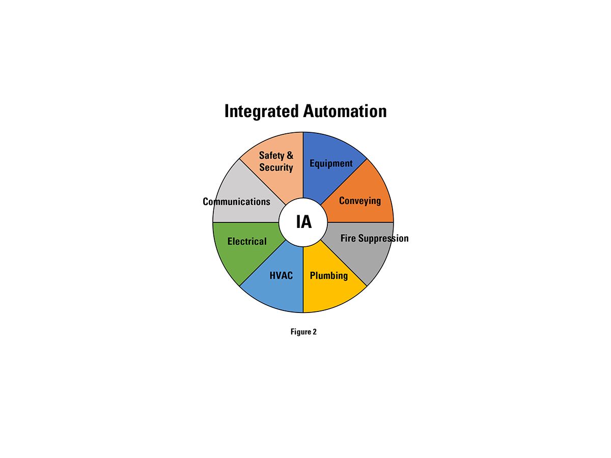
As building technology advances, having separate control networks for each system becomes more expensive and complex. Owners are asking for more features and integration to reduce operating costs and simplify operations. We have come a long way from pneumatic controls, and the pace of change is accelerating. The next step is to knock down the silos of disciplines that still are doing their own thing, and instead start thinking holistically (see Figure 2).
Standards for Integration
Electrical and HVAC design integration is guided by standards such as those developed by Construction Specifications Institute (CSI), the Electronic Components Industry Association (ECIA), and the Consumer Electronics Association (CEA).
CSI Division 25, Integrated Automation, covers systems including building automation, energy-management optimization, lighting, room scheduling, fire detection and suppression, security, information technology (IT)/telecommunications, elevators, audio/video systems, and others. According to CSI, IA systems should be able to include renewable energy monitoring and control and be designed for single or multiple buildings.
CSI Division 25 also specifies that a building's IA system integrate the subsystems represented by the CSI Master Format Facilities Subgroup, which includes:
- Division 11—Equipment.
- Division 14—Conveying Systems.
- Division 21—Fire Suppression.
- Division 22—Plumbing.
- Division 23—HVAC.
- Division 26—Electrical.
- Division 27—Communications.
- Division 28—Electronic Safety & Security.
The CSI Division 25 specification includes common work for operation and maintenance, cabling, commissioning, network devices, instrumentation and terminal devices, control of equipment, and control sequences. Field devices, such as sensors, transmitters, and control valves, are typically connected to their respective local control panels, which communicate with the monitoring and control hardware.
In the future, an IoT device may connect to the backbone and communicate with the integrated building systems. There are wireless remote sensors and switches that make it easy to retrofit existing buildings or add a control point. The IA servers and switches could be co-located with the IT servers. An operator workstation that could monitor all the integrated systems would save space and time spent training operators on multiple systems.
For building controls integration, the ECIA and CEA have jointly adopted EIA/CEA 709.1-B-2002: Control Network Protocol Specification as an open-architecture building controls standard. This standard is approved by ANSI and was originally developed by Echelon Corp. (Echelon's LonTalk, the communications protocol that allows LonWorks-compatible control devices to communicate with one another, is based on this standard.)
Open-architecture control systems have hardware and software specifications that are public information, and available to third parties to develop equipment and software for the open system. Other communication standards are Modbus, BACnet, and proprietary standards. The norm is proprietary building automation, fire alarm, security, and other systems, which restricts the amount of practical integration. Regardless of the building controls standard used, cybersecurity must be addressed in the IA system design, specifications, and operations.
The electrical, HVAC, communication, and security designers should discuss the IA and network standards with each other and building owners-and agree on which ones to use on the project. This enables them to select and schedule equipment and reduce IA communication problems and the need for network gateways. The different systems need to be able to communicate to synergize the gathered information.
As an example, a radio-frequency identification (RFID)-tagged employee badge could initiate the access-control system to communicate with three other building systems provided by different contractors, sending the signals that could turn on the designated lights, activate the occupied setpoints, call the elevator to the entry level, and log the employee number.
The integrated automation system could be provided by the building management/automation system (BMS/BAS), the electrical contractor, or an independent integration contractor. Many of the large electrical equipment suppliers have vertically integrated BAS into the services and built communications and metering into their equipment. This is a trend in the global integrated automation field, with a growing market.
Varying Levels of Complexity
Integration of the electrical and HVAC designs can be accomplished on projects of all sizes, with the level of complexity varying by project type.
Data centers, for example, require a high level of integration of the electrical and HVAC designs. The redundancy of electrical services, chillers, air conditioning units, and standby generators adds to the complexity of the tasks.
For this type of project, a risk assessment should be done to determine the single point of failure of the electrical and HVAC system. A double-ended unit substation is going to require cooling to operate within its design temperature limits, but you don't want a piping leak to spray on the electrical equipment. The HVAC controls should have redundancy and an uninterruptable power supply that is backed up by the standby power. Motor control centers (MCC) with NEMA Class II B or II C wiring can integrate the starters, variable frequency drives (VFDs), overcurrent protective devices, transformer, and branch-circuit panelboard with interlock and interconnect wiring factory-installed.
Controls and programmable logic controllers (PLCs) can be included in the MCC lineup. The MCC can save space, reduce field wiring, and simplify maintenance.
In health care, a patient room with integrated nurse call, lighting controls, window-shade controls, and remote control of temperature setpoints will make for a better patient experience. The temperature setpoint could be adjusted by the TV remote control and on-screen app or by a wireless controller. The electrical lighting controls, HVAC temperature controls, nurse call, and TV systems would have to be integrated and able to communicate with each other.
For smaller projects, which may not justify the cost of a full Division 25 Integrated Automation system, some integration of Division 23 and Division 26 controls can be specified. Networked lighting controls can be partially integrated with the BAS. The occupancy sensor and daylight sensor in an office could send their output signal to a networked room controller. The room controller could dim the lights in response to daylight availability and turn off the lights and controller receptacles after occupants leave. The room controller could send a signal to the lighting control central equipment when the room is unoccupied. The central equipment could communicate via BACnet to the BAS equipment that the space is unoccupied.
The BAS could send a signal to a dedicated outdoor air system (DOAS) to reduce the outdoor air ventilation rate, and then reset the room heating and cooling variable air volume (VAV) box cubic feet per minute. The BAS could receive a demand-response signal from the utility smart grid to limit the energy to the air conditioning equipment and transmit a BACnet message to all the room controllers to dim the lighting. The BAS could be the master time clock and schedule the lighting through the lighting central control equipment. The additional cost to accomplish this integration is a network cable between the room controllers and a cable between the lighting central control equipment and BAS, plus the programming of the sequence of operation.
Technologies and Approaches
Electrical and HVAC designers should consider an integrated system that reduces complexity and space requirements, saves energy, improves reliability, and potentially saves costs. Various technologies and approaches can be used to accomplish these goals including:
Electronically Commutated Motors—ECMs provide variable-speed control with the rectifier/controller being part of the dc's permanent magnet motor. The integration provides space savings for individually mounted VFDs when compared with standard induction motors.
ECMs are commonly configured in fan arrays due to their typical horsepower limitations. ECM efficiency ranges from 70% to 85% versus 40% to 80% for 3-phase motors and 30% to 70% for single-phase motors. ECMs have better part-load efficiency than NEMA Premium motors of equal size, and the motor controller provides protection against overload, phase loss, overheating, and power surges.
The ECM can be soft-started to limit the starting inrush required when on a standby generator, and the controller can accept a 0 to 10 Vdc, or a Modbus signal sent from the BMS to control the speed, typically in the range of 10% to 100%. A simple 0 to 10 Vdc signal will provide a linear 0% to 100% speed control. Modbus communications are bidirectional, so the motor rotations per minute and temperature can provide feedback to provide better and more accurate control sequences.
Currently available ECMs are limited in kilowatt capacity to 11 kW (15 hp). Fan arrays of multiple modular ECMs can be designed to match the capacity required. The fan array provides redundancy in motors and controllers, so if one motor fails the others can remain functional. To obtain redundancy for a VAV air handler with VFD would require at least two fans and two VFDs. The VFDs can be specified with communication cards and digital energy meters to integrate with the IA system.
The modular fan assembly simplifies replacement in tight spaces. The HVAC equipment specification can include an integrated common fan-array disconnect, ECMs, and Modbus controls compatible with the BMS. The integrated equipment eliminates the electrical starter/VFD and motor wiring, which saves space and complexity.
Integration of the VAV Air Handling System Controls with the BMS, Power Monitoring, and Fire Alarm Systems—The control sequence would be specified in CSI Division 25 for setpoints, occupancy schedule, prealarms, alarms, preventive-maintenance notifications, and energy usage. The power metering can be used as an input to a demand-response control sequence that could dim the lighting, reset the temperature setpoint, limit the chiller-input power, and reduce the air handling cubic feet per minute to limit the electrical peak demand. The IA system can centrally monitor and display the systems in a common format to reduce the training time of operators (see Figure 3).
Using the Same Backbone for Multiple Purposes—Sharing a high-speed backbone can reduce installation and maintenance costs but may create security and maintenance conflicts. The shared backbone, cable trays, and pathways could be specified in the CSI Division 25 05 00: Common Work Results for Integrated Automation.
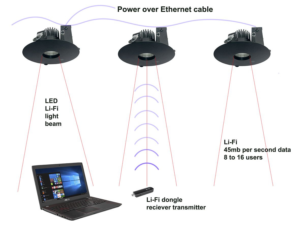
Using Light to Transmit Data and Internet—LED lighting luminaires are coming to market with light fidelity (Li-Fi) wireless communications, using visible light, infrared, or ultraviolet spectrums instead of radio frequency (Wi-Fi). The lights may receive their power and communications over a single Ethernet cable (Power over Ethernet, or PoE). Even when the lights are perceived as off by the eye, full data-communications rates are possible.
Some luminaires also integrate occupancy sensors and temperature/humidity sensors, which reduces wiring costs for the integrated lighting, lighting controls, data, security, and HVAC control systems. The Li-Fi communications are line-of-sight, so the coverage is the same as the light distribution and fewer users share a data channel, which will provide higher transmission rates. The Li-Fi is also more secure because it does not transmit through opaque walls (see Figure 4).
Geofencing—This location-based app or software uses GPS, RFID, Wi-Fi, or cellular data to trigger a preprogrammed action when a mobile device or RFID tag enters or exits a virtual boundary setup around a geographical location. Geofencing could be used with an IoT smart thermostat, for example. When the geofence senses an RFID tag or wireless device is present, the occupied control sequence would be activated. The occupied sequence could be specified to set the temperature or increase the ventilation rate (as well as activate occupancy-controlled plug loads, set a lighting level and color temperature by time of day, and control motorized shades).
Lot or Networked Electrical Energy Meters—These can provide real-time energy usage and peak demand and verify electrical billing. The display of energy usage to the occupant also has been shown to reduce energy consumption. The submeters can be used as measurement and verification of energy-conservation measures. The digital meters can monitor individual feeder breakers or panelboard circuits, so you can get data for U.S. Green Building Council's LEED measurement and verification EAC5.
Power-quality Meters—These can capture and analyze voltage spikes, dips, and harmonic distortion, which are detrimental to electronic equipment. Having the electronic meters networked guarantees that meters will be read on a continuous basis and allows the real-time information to be used by multiple subsystems to send warnings and alarms via wireless devices for operations and maintenance. Peak-demand data could tell the BMS that the systems should be adjusted to prevent creating a new electrical peak demand. The meters also could be used for decisions about load-shedding of noncritical loads when operating on a standby generator. The IA system may be programmed to allow a smaller generator to be installed and serve the building by load-shedding and demand-limiting the electrical and HVAC systems.
Optimizing BIM
The project's BIM model—when fully used—contributes greatly to the integration of electrical and HVAC designs. The BIM equipment model, for example, would include the properties required for the HVAC electrical and IA specification and schedules used during design development, construction documents, and testing and commissioning. BIM models should have actual equipment dimensions, coil-pulling clearances, and working clearances to assist in coordination and code-compliant installation. The BIM properties could be linked to the different schedules to assist in coordination, so for example, when the mechanical designer changes a horsepower, the electrical-panel schedule updates.
The electrical properties would include voltage, number of phases, apparent load volt-amps, starter or controller type, and disconnect type. Electrical equipment working clearances and dedicated spaces above switchboards, panelboards, motor controls, and equipment should be included. The HVAC designer can use the BIM model to calculate the heating and cooling loads for a space, including the designed lighting load. The space-occupancy lighting controls can be integrated with the BMS and HVAC controls to switch from unoccupied to occupied control sequences, optimizing energy savings in the annual energy-modeling software.
Good for Owners and Occupants
The main drivers for IA include energy costs, more complex buildings, managing large facilities with fewer full-time staff, remote management, and analyzing more data to make better decisions. Occupant expectations for comfort and communications also drive the expansion of IA as more people understand what a smart building should provide. IA also will expand as communication networks grow faster and less expensive per point.
Through collaborative planning and using the various tools and technologies available, electrical and HVAC designers can contribute to any building's IA by optimizing the integration of their respective systems. By doing so, they create a design that occupies less space, lowers installed costs, and reduces energy and operating costs—all good news for the owner.
John McGonegle is a senior electrical engineering specialist with IMEG Corp. He is responsible for the firm's electrical design quality and technical knowledge and provides quality control reviews.


