Grounded systems are typically preferred to ungrounded systems for several reasons. Grounded systems stabilize voltage levels throughout the system, ensuring that all equipment in the system operates under the same potential difference. This is particularly important for a UPS, as it is tasked with precisely regulating voltage levels both at its output and on its dc bus, and accurate voltage regulation requires a solid, stable reference to ground to maintain. Grounded systems also mitigate voltage spikes due to lightning strikes, help prevent potential differences between different pieces of equipment in the system, and provide a circuit for ground-fault current to flow through the grounded circuit conductors back to the supply source, allowing overcurrent protective devices to quickly operate and isolate the fault.
NFPA 70: National Electrical Code (NEC), Article 250.4, provides general, performance-based requirements for both grounded systems in 250.4(A) and ungrounded systems in 250.4(B). Grounded systems have five requirements: electrical system grounding, grounding of electrical equipment, bonding of electrical equipment, bonding of electrically conductive materials, and effective ground-fault current paths.
Notably, the four requirements of ungrounded systems listed in 250.4(B) are similar or identical to the latter four requirements of grounded systems. Just as in grounded systems, ungrounded systems require that noncurrent-carrying conductive materials enclosing electrical conductors or equipment, and those that are likely to become energized, be connected to the ground through a low-impedance path. The overlap between these two sets of requirements illustrates the notion that designing an ungrounded system is not too terribly different than designing a grounded one.
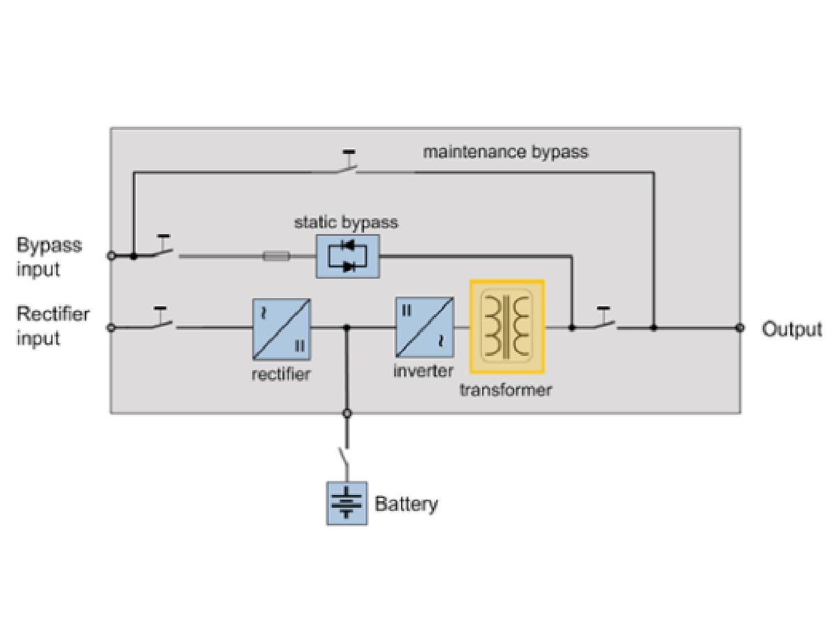
To understand what the NEC requires of a transformerless UPS system when it is operating ungrounded during battery discharge, we must first identify how this system is defined using the language of the NEC. When the UPS input circuit breaker is open, the UPS is not connected to the upstream power system, and therefore to the supply service, through any circuit conductors other than those used for grounding and bonding.
It is important to note that even though the UPS enclosure and downstream equipment may still be effectively bonded to the supply-source enclosure in this condition, the system is not considered grounded unless a current-carrying conductor is connected to ground. Therefore, the NEC defines the system in this state as a separately derived system and the UPS batteries as a separately derived source. The grounding requirements for ungrounded separately derived systems are defined in Article 250.30(B).
This section of the NEC requires three components: grounding electrode conductor, grounding-electrode system, and supply-side bonding jumper. The latter of these components is only required when the source of a separately derived system is located in a separate enclosure than the first disconnecting means. This will usually not be the case for a UPS, as the output circuit breaker of the UPS is normally housed in the UPS enclosure.
All three of these grounding components are required in grounded separately derived systems as well. Essentially, the UPS enclosure must be connected to ground through the building's grounding-electrode system by way of a grounding electrode conductor. This connection in an ungrounded system serves as the grounding reference point for all conductive equipment in the ungrounded system that does not carry current under normal conditions.
Grounding the System
UPS manufacturers have a variety of solutions for the issue of how to ensure the UPS maintains a reference to the ground during ungrounded conditions, to ensure that the UPS voltage regulation remains stable. Some manufacturers derive a so-called "virtual ground" at the common point of the input and output filters of the UPS to achieve this purpose. This is often a standard feature, especially on newer UPS models, but an optional accessory is required in some cases. When specifying a transformerless UPS, especially in a 3-phase, 3-wire system, take care when considering how it will operate under ungrounded conditions.
The rules governing the grounding-electrode system and grounding electrode conductors are found in Part III of Article 250 of the NEC. The same grounding-electrode system used for the building as a whole must also be used for any separately derived systems, as per NEC 250.58, so all that is required is a connection between the building's grounding electrode and the UPS enclosure through a grounding electrode conductor. Accordingly, all of the normal requirements for grounding-electrode system materials listed in NEC 250.52 and installation listed in 250.53 apply in this situation.
Similarly, the rules governing grounding electrode conductors are not different between grounded and ungrounded systems. NEC Articles 250.62 and 250.64 govern the materials and installation methods of grounding electrode conductors, respectively. The required size of the grounding electrode conductors used must be determined through the requirements of NEC 250.66, which vary based on the type of grounding electrode used, the size of the largest ungrounded conductor or set of conductors in the system, and the material of the grounding electrode conductor.
No matter the size of the system, the grounding electrode conductor must always be at least as large as #8 AWG for copper or #6 AWG for aluminum, and unless superseded by local amendments or authority having jurisdiction (AHJ) requirements, the grounding electrode conductor is not required to be larger than #3/0 AWG for copper or 250 kcmil for aluminum. Finally, requirements for bonding grounding electrode conductors to the grounding-electrode system are covered in NEC 250.68.
Ungrounded Systems
Thus far, the grounding rules discussed covering ungrounded systems are very similar to those covering grounded systems. Indeed, if one employs a robust grounding design for a normally grounded system and ensures that the UPS and battery-cabinet enclosures are connected to the building's grounding-electrode system through appropriately sized grounding electrode conductors, almost all requirements for an ungrounded system will be met when the UPS discharges its batteries and becomes an ungrounded system during power transfer.
However, there is a key difference between the behavior of grounded and ungrounded systems that imposes an additional requirement on ungrounded systems. This difference appears when a single line-to-ground fault occurs in the system.
In a solidly grounded system, the connection of (usually) the neutral wire to ground at the supply source means that a complete circuit will be formed when a line-to-ground fault occurs. This allows a large amount of fault current to flow through the low-impedance path created by the fault, causing an overcurrent protective device (OCPD) equipped with ground-fault detection to operate and quickly isolate the fault.
In an ungrounded system, though, there is no circuit created when a single line-to-ground fault occurs through which fault current can flow. Instead, the faulted conductor simply becomes grounded and the line-to-line potentials between the faulted phase and the other unfaulted phases become line-to-ground potentials. The value of the potential difference between the phases, however, does not change. This will not have a noticeable effect on the system's performance when it occurs, but if the fault is left unrepaired and a second line-to-ground fault occurs, this will result in a double line-to-ground fault, drawing larger fault currents and creating the potential for greater damage to electrical equipment and greater risk to personnel safety. As in grounded system, a phase-to-phase fault in an ungrounded system will generate fault current and will typically cause an overcurrent protective device to operate and isolate the fault.
To ensure that single line-to-ground faults do not go undetected, NEC 250.21(B) requires that ungrounded systems be outfitted with ground detectors at a point as close as practicable to the system supply source. A ground detector monitors the potential difference between the phase conductors of the system and the ground in the ungrounded portion of the system to which it is connected. If a ground fault is present in the system, it emits a visual and/or audible signal to alert operators or maintenance personnel. The operators can then initiate an orderly shutdown of the system so that the fault can be located and repaired. This is especially important in a system served by a UPS, as orderly shutdowns to critical loads are generally necessary to minimize risk to life safety or disruption to business functions.
For example, it may be costly to initiate a shutdown of a critical computer system due to the presence of a ground fault on the system, but it will certainly be less so than an abrupt disconnection of power to those same computers. Most UPS systems will contain a ground-detection mechanism, but it is important to verify this component is included to ensure compliance with this requirement.
Detection of ground faults is especially important when a system becomes temporarily ungrounded, such as while a transformerless UPS is discharging its battery due to an input source failure, because it is likely to become grounded again when the input power returns. When power is restored, either through a return of the utility source or due to a generator source coming online, the UPS input circuit breaker will close and the system will once again be grounded. If a ground fault is still present in the system when this occurs, ground-fault current will flow through the fault. A ground detector in the UPS can prevent this situation through a pre-emptive shutdown before fault current has a chance to flow.
Detection
To ensure that a ground-fault detector can operate correctly throughout the ungrounded system, it is important to verify compliance with the requirements for connection of the UPS enclosure to the grounding-electrode system (discussed above), as well as the requirements for bonding of metallic objects that do not carry current, covered in Part V of NEC Article 250. This ensures that any point on the ungrounded system at which a ground fault is likely to occur has a solid reference to the ground by way of the UPS enclosure's connection to the grounding-electrode system, and that the detector can accurately detect a ground-fault condition.
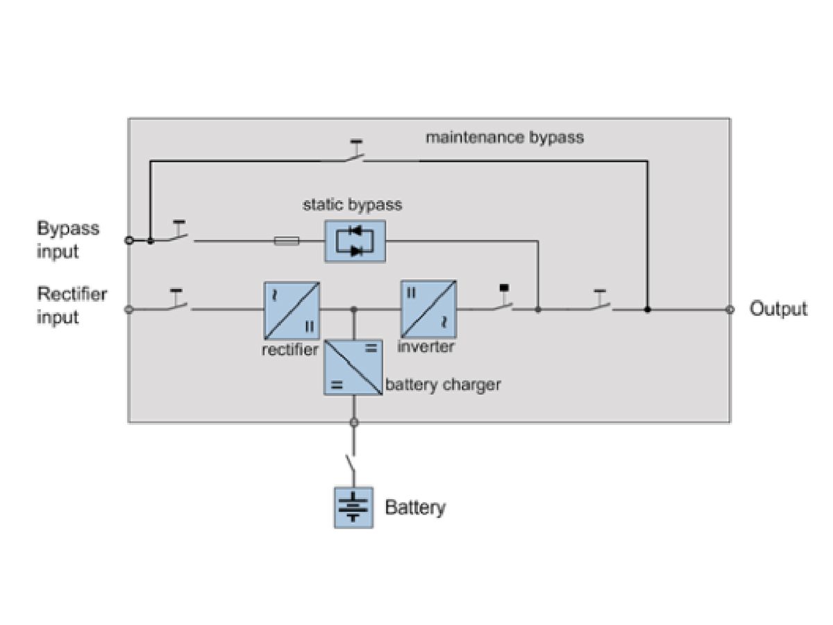
In addition to the requirements for ungrounded ac systems, the NEC contains additional requirements for ungrounded dc systems. This applies to the more common 2-wire dc system, as Section 250.162(B) requires that all 3-wire dc systems be grounded. Of course, a UPS will contain a dc system, namely the connection between the energy-storage system and the output inverter. NEC Article 250.169 lists the requirements for an ungrounded dc separately derived system. These requirements are similar to those of the ac system, namely that the source enclosure be grounded through the building's grounding-electrode system by way of a grounding electrode conductor.
Note, though, that the sizing of the grounding electrode conductor for a dc system is governed by a different section than that of an ac system, namely Section 250.166, which requires that the grounding electrode conductor not be smaller than the largest conductor supplied by the dc system. However, the same minimum- and maximum-required grounding electrode conductor sizes for various installations apply to both dc and ac systems. With most UPS installations, no special considerations are required for the dc system, as typically the dc system is grounded at the battery enclosure, though it is important to verify this will be the case in a given installation.
In the event that special design considerations do need to be made, to consider what may constitute the best practice for designing the grounding system for the dc portion of a UPS during ungrounded system conditions, it may be useful to consider a somewhat analogous situation: an ungrounded solar photovoltaic system.
Ungrounded photovoltaic systems are not uncommon for many of the same reasons that transformerless UPS systems have become popular. Similar to the dc portion of a UPS system during power transfer, an ungrounded photovoltaic system is an ungrounded dc system supplying an ac system through an inverter. In fact, most photovoltaic systems have energy-storage systems as part of the dc system, just as in a UPS. So while they are not requirements, the rules and commentary of the NEC regarding photovoltaic systems contained in Article 690, particularly Part III and Part V, can be instructive in thinking about grounding of the UPS energy-storage system.
Of particular note is Section 690.15(D), which describes the requirements of equipment-disconnecting means for photovoltaic systems. This section draws attention to a more general requirement found in Section 210.4(B), which requires that disconnecting means must simultaneously disconnect all ungrounded conductors of the circuit to which it is connected. Unlike a grounded system, in which the disconnection of the neutral wire does not need to be simultaneous with the disconnection of the phase wires, in an ungrounded system all wires must be simultaneously disconnected, as none are grounded. This is not often a concern, but it is something to keep in mind when specifying the dc circuit breaker protecting the energy-storage system of the UPS.
Ben Stevens is an associate electrical engineer at Page. He has worked for Page for 3 years and specializes in science and technology projects.


