Sizing Gensets
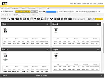
It is generally good practice to size the paralleling system using generator-sizing software and request the help of a manufacturer’s representative. Many factors influence genset sizing, making it time-consuming to manually calculate required generator capacity. Sizing software available from the major power-generation manufacturers will greatly simplify this process and allow for analysis of alternatives to optimize the generator size. Parameters that determine the required generator set size include minimum generator set load, maximum allowable step voltage dip and step frequency dip, altitude and temperature, duty cycle, fuel, phase, frequency, and voltage. It is important to identify every type and size of load the generator set will power. Additionally, when nonlinear loads are present, it may be necessary to oversize the alternator.
The more you know about the parameters that affect sizing, the better off you will be. The following is a general discussion of how various loads and electrical factors affect the sizing of generator sets.
Single-phase Loads and Load Imbalance. Single-phase loads should be distributed as evenly as possible between the three phases of a 3-phase generator set to fully use generator set capacity and limit voltage imbalance.
Peak Loads. Peak loads are caused by loads that cycle on and off, such as welding equipment, medical imaging equipment, or motors. Depending on how cyclic loads are taken into account, the generator size could significantly increase or decrease the size of the recommended generator set despite painstaking efforts to place loads in a step starting sequence.
Motor Loads. Calculating specific motor loads is best handled by sizing software that will convert types of motors into load-starting and -running requirements. All motor loads greater than 50 hp should be modeled. A large motor with high inrush current may cause a generator voltage dip, which would affect other sensitive systems. The manner in which generator voltage recovers from this dip is a function of the relative size of the generator. Depending on the severity of the load, the generator should be sized to recover to rated voltage within a few seconds, if not cycles. Various types of reduced-voltage motor starters are available to reduce the starting kVA of a motor in applications where reduced motor torque is acceptable. Reducing motor-starting kVA can reduce the voltage dip, the size of the generator set, and provide a softer mechanical start.
Battery-charger Loads. A battery charger is a nonlinear load requiring an oversized alternator based on the number of rectifiers (pulses)—up to 2.5 times the steady-state running load for three-pulse loads and up to 1.15 times for 12-pulse. These loads are typically found in telecommunications systems.
Uninterruptible Power Supply (UPS) Loads. Another type of nonlinear load, the UPS system uses rectifiers or other static devices to convert ac voltage to dc voltage for charging storage batteries. Larger alternators are required to prevent overheating due to the harmonic currents induced by the rectifiers and to limit system voltage distortion by lowering alternator reactance.
Medical Imaging Loads. These include CT scan, MRI, and X-ray equipment. The generator set should be sized to limit the voltage dip to 10% when the medical-imaging equipment is operated with all other loads running to protect image quality.
Lighting Loads. In addition to lamp wattages, all ballast wattages and starting/running power factors should be considered.
Regenerative Loads. For loads such as elevators, cranes, and hoists, the power source is often relied on for absorbing power back fed during braking. That is usually not a problem when the utility is supplying power, because it can be considered as an infinite power source with many loads. A generator set, in comparison, is able to absorb far less power, especially with no other loads connected. Generally, the regeneration problem can be solved by making sure there are other connected loads that can absorb the regenerative power. Excessive regenerative load can cause a generator set to overspeed and shut down.
Future Needs
A last step in the sizing equation has to do with future needs. Power use is not always fixed and tends to grow over time. Therefore, any generator set sizing exercise needs to take system expansion into consideration. Even with sophisticated software solutions, the final decision on generator set size needs to be tempered with judgment.
Case Study: Graton Standby Generator System
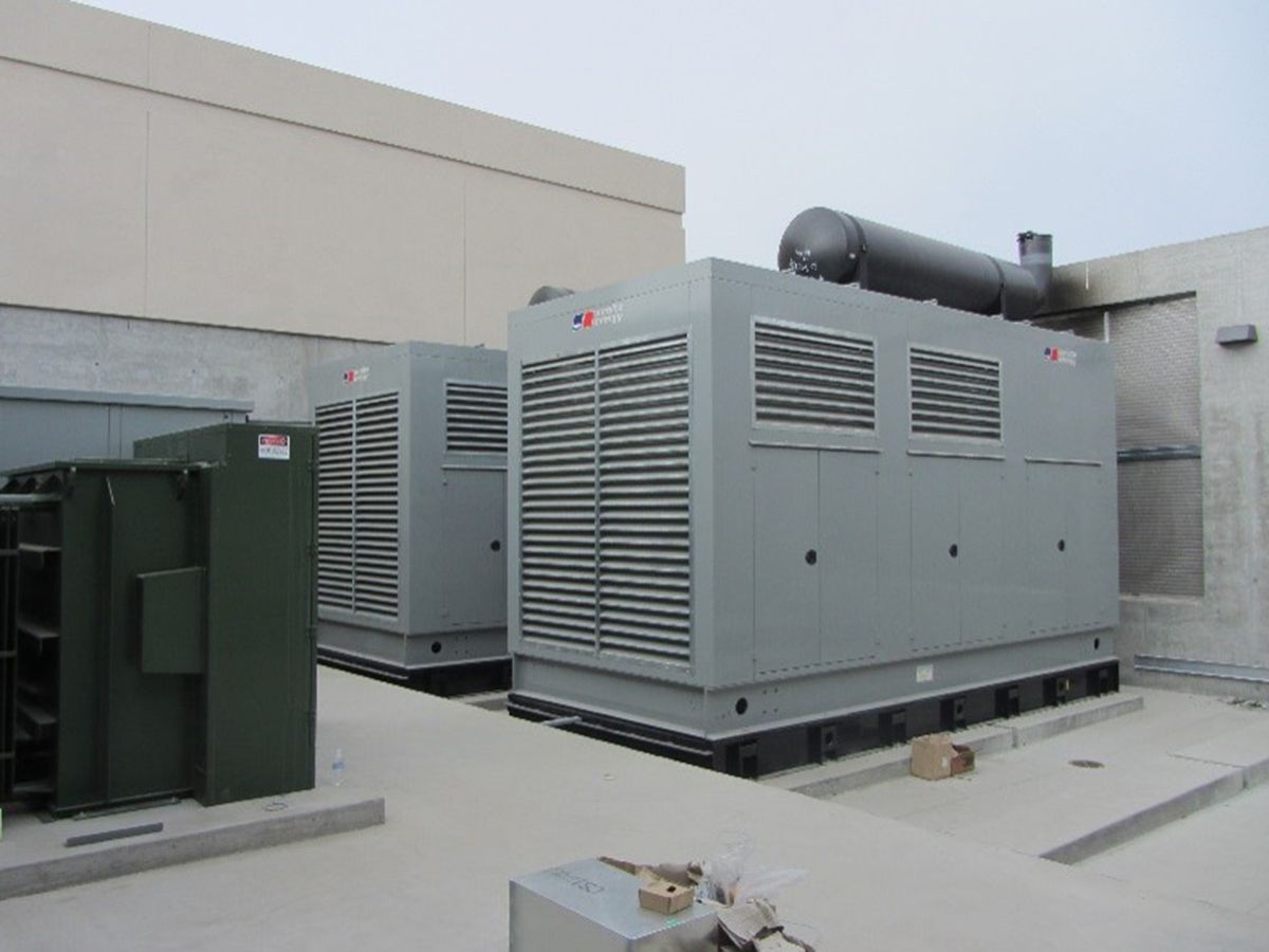
Graton’s emergency/optional standby system is smaller than Encore’s generator system, but it is also built as a robust backup system. Initially during Phase 1, the generator system had two 1,500-kW generators with provision for a third generator. During Phase 2 construction, a third 1,500-kW generator was installed, illustrating the ease of expanding a paralleling generator system. The generators are located outside the building (see Figure 3). Each generator is equipped with pad-mounted transformers to step up the generator output voltage from 480 V to 21.6 kV, a sound-attenuating weatherproof enclosure, and a 1,000-gal subbase tank. The paralleling system PSG has a dual-bus paralleling switchgear system with one incoming utility feeder and prioritized-output feeder breakers.
At Graton, the emergency and business-critical loads are categorized as:
1. Emergency Loads:
- Egress lighting
- Fire and life safety loads
- Fire pump
- Elevators (one per bank)
- Smoke-management equipment
- Essential communications systems
- Lighting for electrical, mechanical, telecommunications, and similar spaces.
2. Business-critical Loads:
- Gaming tables
- Slot machines
- Slot data systems
- Telecommunications rooms
- Refrigeration racks
- UPS systems
- Casino lighting
- Data center
- HVAC and central plant components associated with gaming activities.
3. Important Paralleling Features Include:
- Dual bus: one for the generators and the second for the load bus, thereby allowing generator testing without affecting the building loads. During generator testing, the loads are powered by utility power.
- Dual hot-backup PLCs and battery systems
- Remote generator system control cabinets
- Redundant pathway for power
- If one generator fails, then the lowest business-critical priority, Priority 4, will be load shed to ensure that the generator bus voltage and frequency is stabilized and within acceptable parameters. The emergency loads and most of the business-critical loads should remain on standby power.
- If two generators fail, then all nonemergency loads shall be load shed to ensure that the emergency system has a reliable source of power.
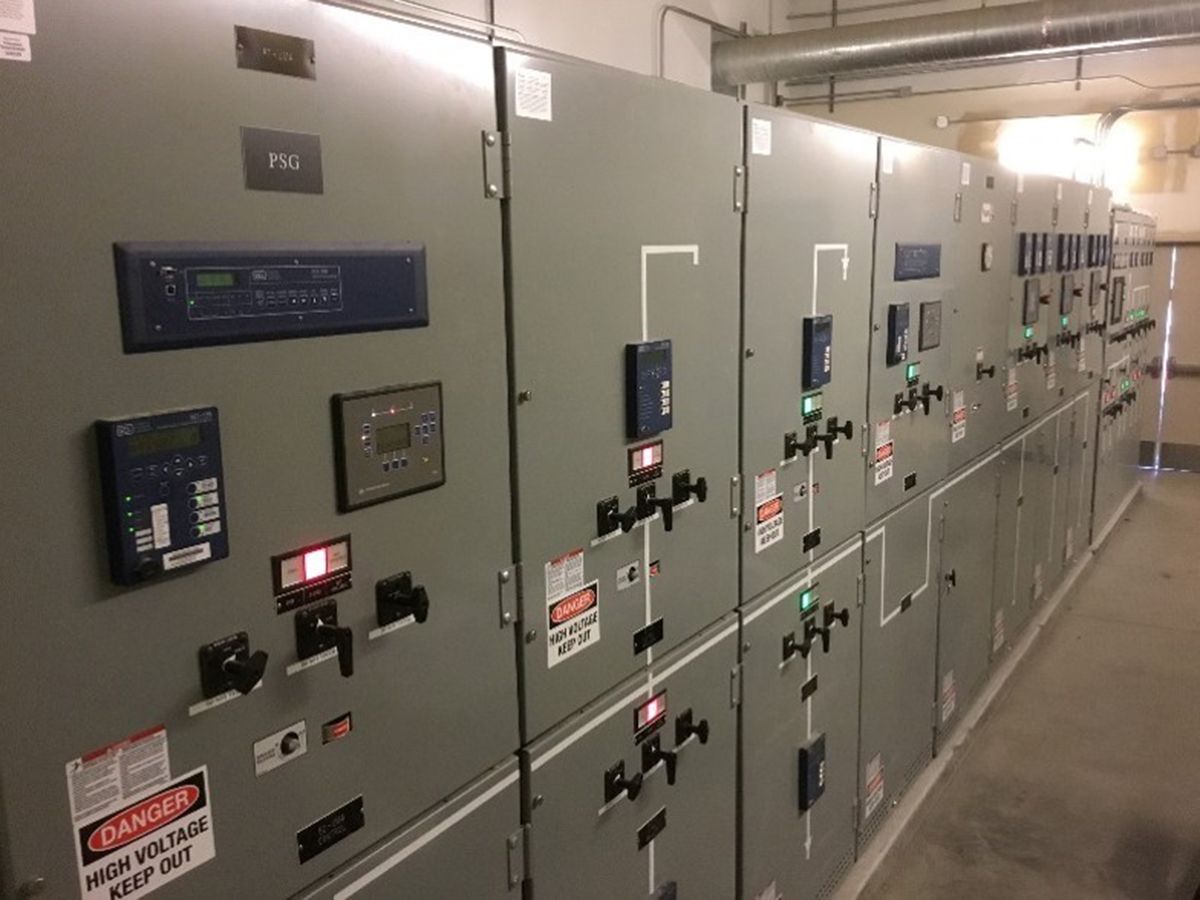
Downstream of the PSG, the load distribution system has switchgears equipped with dual-source auto-transfer mechanisms that automatically transfer the source power from the PSG and the other power direct from utility distribution (see Figure 4). The emergency and optional standby loads also have dual-sourced auto-transfer mechanisms. However, the primary source is the feeder from the generator bus. This arrangement allows for maintenance shutdown of paralleling switchgear and also provides the facility staff options for alternative feed arrangements to restore operation in the event of a system failure.
Leslie Fernandez is senior project engineer, electrical at JBA Consulting Engineers. He has more than 30 years of engineering and design and field experience including medium-voltage distribution systems for military, mining, tunneling, food manufacturing, power-production facilities, high-rise facilities, and casino-resort complexes.


